Facebook
 Google
 GitHub
 Linkedin
AC Electric Circuits
Mixed-Frequency Signals
31 questions By Tony R. Kuphaldt
-
Question 1 of 31
What is a harmonic frequency? If an oscillator circuit outputs a fundamental frequency of 12 kHz, calculate the frequencies of the following harmonics:
- 1st harmonic =
- 2nd harmonic =
- 3rd harmonic =
- 4th harmonic =
- 5th harmonic =
- 6th harmonic =
Reveal answer- 1st harmonic = 12 kHz
- 2nd harmonic = 24 kHz
- 3rd harmonic = 36 kHz
- 4th harmonic = 48 kHz
- 5th harmonic = 60 kHz
- 6th harmonic = 72 kHz
Notes:Ask your students to determine the mathematical relationship between harmonic number, harmonic frequency, and fundamental frequency. It isn’t difficult to figure out!
-
Question 2 of 31
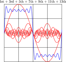
An interesting thing happens if we take the odd-numbered harmonics of a given frequency and add them together at certain diminishing ratios of the fundamental’s amplitude. For instance, consider the following harmonic series:
(1 volt at 100 Hz) + (1/3 volt at 300 Hz) + (1/5 volt at 500 Hz) + (1/7 volt at 700 Hz) + . . .
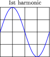
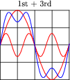
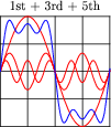
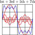
Here is what the composite wave would look like if we added all odd-numbered harmonics up to the 13th together, following the same pattern of diminishing amplitudes:
If we take this progression even further, you can see that the sum of these harmonics begins to appear more like a square wave:
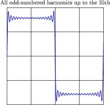
This mathematical equivalence between a square wave and the weighted sum of all odd-numbered harmonics is very useful in analyzing AC circuits where square-wave signals are present. From the perspective of AC circuit analysis based on sinusoidal waveforms, how would you describe the way an AC circuit “views” a square wave?
Reveal answerThough it may seem strange to speak of it in such terms, an AC circuit “views” a square wave as an infinite series of sinusoidal harmonics.
Follow-up question: explain how this equivalence between a square wave and a particular series of sine waves is a practical example of the Superposition Theorem at work.
Notes:If you have access to a graphing calculator or a computer with graphing software installed, and a projector capable of showing the resulting graph(s), you may demonstrate this square-wave synthesis in front of the whole class. It makes an excellent illustration of the concept.
Discuss this with your students: that the relatively simple rules of AC circuit analysis (calculating reactance by ωL and [1/(ωC)], calculating impedance by the trigonometric sum of reactance and resistance, etc.) can be applied to the analysis of a square wave’s effects if we repeat that analysis for every harmonic component of the wave.
This is truly a remarkable principle, that the effects of a complex waveform on a circuit may be determined by considering each of that waveform’s harmonics separately, then those effects added together (superimposed) just as the harmonics themselves are superimposed to form the complex wave. Explain to your students how this superposition principle is not limited to the analysis of square waves, either. Any complex waveform whose harmonic constituents are known may be analyzed in this fashion.
-
Question 3 of 31
In the early 1800’s, French mathematician Jean Fourier discovered an important principle of waves that allows us to more easily analyze non-sinusoidal signals in AC circuits. Describe the principle of the Fourier series, in your own words.
Reveal answer- “Any periodic waveform, no matter how complex, is equivalent to a series of sinusoidal waveforms added together at different amplitudes and different frequencies, plus a DC component.”
Follow-up question: what does this equation represent?
f(t) = A0 + (A1 sin ωt) + (B1 cos ωt) + (A2 sin 2ωt) + (B2 cos 2ωt) + ... Notes:So far, all the “tools” students have learned about reactance, impedance, Ohm’s Law, and such in AC circuits assume sinusoidal waveforms. Being able to equate any non-sinusoidal waveform to a series of sinusoidal waveforms allows us to apply these “sinusoidal-only” tools to any waveform, theoretically.
An important caveat of Fourier’s theorem is that the waveform in question must be periodic. That is, it must repeat itself on some fixed period of time. Non-repetitive waveforms do not reduce to a definite series of sinusoidal terms. Fortunately for us, a great many waveforms encountered in electronic circuits are periodic and therefore may be represented by, and analyzed in terms of, definite Fourier series.
It would be good to mention the so-called FFT algorithm in this discussion while you’re on this topic: the digital algorithm that computers use to separate any sampled waveform into multiple constituent sinusoidal frequencies. Modern computer hardware is able to easily implement the FFT algorithm, and it finds extensive use in analytical and test equipment.
Related Tools:
- Intermediate Electromagnetism and Electromagnetic Induction
- Performance-Based Assessments for Network Analysis Competencies