Facebook
 Google
 GitHub
 Linkedin
Analog Integrated Circuits
Open-Loop OpAmp Circuits
19 questions By Tony R. Kuphaldt
-
Question 16 of 19
Explain what a window comparator circuit is (sometimes called a window discriminator), and identify at least one practical application for one.
Reveal answerA “window comparator” circuit detects when a voltage falls between two different reference voltages. I’ll let you figure out some practical applications for such a circuit!
Notes:Ask your students where they found the answer for this question, and further explore some of the practical applications they offer.
-
Question 17 of 19
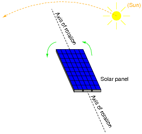
Photovoltaic solar panels produce the most output power when facing directly into sunlight. To maintain proper positioning, “tracker” systems may be used to orient the panels’ direction as the sun “moves” from east to west across the sky:
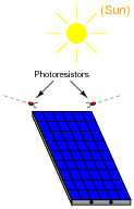
One way to detect the sun’s position relative to the panel is to attach a pair of Light-Dependent Resistors (LDR’s) to the solar panel in such a way that each LDR will receive an equal amount of light only if the panel is pointed directly at the sun:
Two comparators are used to sense the differential resistance produced by these two LDR’s, and activate a tracking motor to tilt the solar panel on its axis when the differential resistance becomes too great. An “H-drive” transistor switching circuit takes the comparators’ output signals and amplifies them to drive a permanent-magnet DC motor one way or the other:
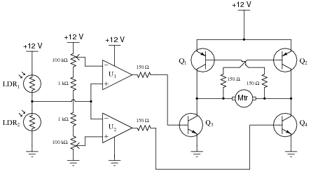
In this circuit, what guarantees that the two comparators never output a “high” ( V) voltage simultaneously, thus attempting to move the tracking motor clockwise and counter-clockwise at the same time?
Reveal answerWith the potentiometers connected in series like this, the upper comparator’s reference voltage will always be greater than the lower comparator’s reference voltage. In order for both comparators to saturate their outputs “high,” the voltage from the photoresistor divider would have to be greater than the upper potentiometer’s voltage and less then the lower potentiometer’s voltage at the same time, which is an impossibility. This comparator configuration is commonly known as a window comparator circuit.
Notes:There is a lot going on in this comparator circuit for you and your students to discuss. Take time to talk about the operation of the entire circuit in detail, making sure students understand how every bit of it works.
If any of your students point out that there seem to be some power supply connections missing from the comparators (U1 and U2), discuss the fact that this notation is often used when multiple opamps or comparators are contained in the same integrated circuit. Often, the power supply connections will be omitted entirely for the sake of simplicity! Since everyone understands that opamps need DC power in order to function, the V and -V (or ground) connections are simply assumed.
One misunderstanding I’ve seen with beginning students is to assume that signal input connections and power connections to an opamp are equivalent. That is, if an opamp does not receive V/-V power through the normal power terminals, it will operate off of whatever voltages appear at its inverting and non-inverting inputs. Nothing could be further from the truth! An ïnput” connection to a circuit denotes a signal to be detected, measured, or manipulated. A “power” connection is completely different. To use a stereo analogy, this is confusing the audio patch cable connections with the power cord.
-
Question 18 of 19
Predict how the operation of this solar panel tracking circuit (where the tracking motor turns in response to a difference in light sensed by the two photoresistors) will be affected as a result of the following faults. Assuming that the motor spins clockwise when its left terminal is negative and its right terminal is positive (when Q2 and Q3 are both on), specify the direction of rotation (or non-rotation) resulting from each fault. Consider each fault independently (i.e. one at a time, no multiple faults):
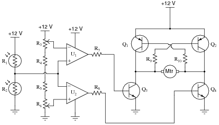
- Photoresistor R1 fails open:
- Photoresistor R2 fails open:
- Resistor R4 fails open:
- Resistor R5 fails open:
- Resistor R7 fails open:
- Resistor R10 fails open:
- Transistor Q3 fails open (collector-to-emitter):
For each of these conditions, explain why the resulting effects will occur.
Reveal answer- Photoresistor R1 fails open: Motor continuously spins counter-clockwise.
- Photoresistor R2 fails open: Motor continuously spins clockwise.
- Resistor R4 fails open: Motor refuses to energize at all.
- Resistor R5 fails open: Motor refuses to energize at all.
- Resistor R7 fails open: Motor cannot spin clockwise, only counter-clockwise.
- Resistor R10 fails open: Motor cannot spin counter-clockwise, only clockwise.
- Transistor Q3 fails open (collector-to-emitter): Motor cannot spin clockwise, only counter-clockwise.
Notes:The purpose of this question is to approach the domain of circuit troubleshooting from a perspective of knowing what the fault is, rather than only knowing what the symptoms are. Although this is not necessarily a realistic perspective, it helps students build the foundational knowledge necessary to diagnose a faulted circuit from empirical data. Questions such as this should be followed (eventually) by other questions asking students to identify likely faults based on measurements.