Facebook
 Google
 GitHub
 Linkedin
AC Electric Circuits
Passive Filter Circuits
44 questions By Tony R. Kuphaldt
-
Question 1 of 44
In very simple, qualitative terms, rate the impedance of capacitors and inductors as “seen” by low-frequency and high-frequency signals alike:
- Capacitor as it “appears” to a low frequency signal: (high or low) impedance?
- Capacitor as it “appears” to a high frequency signal: (high or low) impedance?
- Inductor as it “appears” to a low frequency signal: (high or low) impedance?
- Inductor as it “appears” to a high frequency signal: (high or low) impedance?
Reveal answer- Capacitor as it “appears” to a low frequency signal: high impedance.
- Capacitor as it “appears” to a high frequency signal: low impedance.
- Inductor as it “appears” to a low frequency signal: low impedance.
- Inductor as it “appears” to a high frequency signal: high impedance.
Challenge question: what does a capacitor “appear” as to a DC signal?
Notes:Ask your students how they arrived at their answers for these qualitative assessments. If they found difficulty understanding the relationship of frequency to impedance for reactive components, I suggest you work through the reactance equations qualitatively with them. In other words, evaluate each of the reactance formulae (XL = 2 πf L and XC = [1/(2 πf C)]) in terms of f increasing and decreasing, to understand how each of these components reacts to low- and high-frequency signals.
-
Question 2 of 44
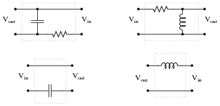
Identify these filters as either being “low-pass” or “high-pass”, and be prepared to explain your answers:
Reveal answer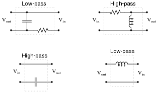
Notes:Low-pass and high-pass filter circuit are really easy to identify if you consider the input frequencies in terms of extremes: radio frequency (very high), and DC (f = 0 Hz). Ask your students to identify the respective impedances of all components in a filter circuit for these extreme frequency examples, and the functions of each filter circuit should become very clear to see.
-
Question 3 of 44
Suppose you were installing a high-power stereo system in your car, and you wanted to build a simple filter for the “tweeter” (high-frequency) speakers so that no bass (low-frequency) power is wasted in these speakers. Modify the schematic diagram below with a filter circuit of your choice:
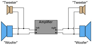
Hint: this only requires a single component per tweeter!
Reveal answer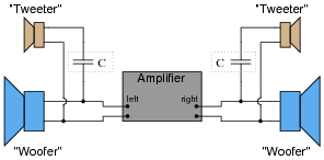
Follow-up question: what type of capacitor would you recommend using in this application (electrolytic, mylar, ceramic, etc.)? Why?
Notes:Ask your students to describe what type of filter circuit a series-connected capacitor forms: low-pass, high-pass, band-pass, or band-stop? Discuss how the name of this filter should describe its intended function in the sound system.
Regarding the follow-up question, it is important for students to recognize the practical limitations of certain capacitor types. One thing is for sure, ordinary (polarized) electrolytic capacitors will not function properly in an application like this!