Facebook
 Google
 GitHub
 Linkedin
High-pass Filters
A high-pass filter’s task is just the opposite of a low-pass filter: to offer easy passage of a high-frequency signal and difficult passage to a low-frequency signal. As one might expect, the inductive (Figure below) and capacitive (Figure below) versions of the high-pass filter are just the opposite of their respective low-pass filter designs:
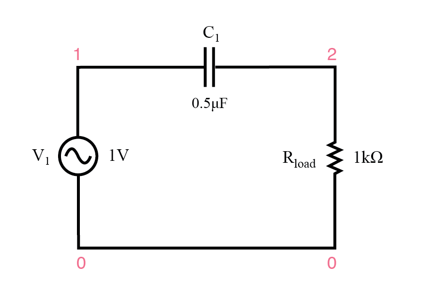
Capacitive high-pass filter.
The Capacitor’s Impedance
The capacitor’s impedance (Figure above) increases with decreasing frequency. (Figure below) This high impedance in series tends to block low-frequency signals from getting to load.
capacitive highpass filter
 v1 1 0 ac 1 sin
 c1 1 2 0.5u
 rload 2 0 1k
 .ac lin 20 1 200
 .plot ac v(2)
 .end

The response of the capacitive high-pass filter increases with frequency.

Inductive high-pass filter.
The Inductor’s Impedance
The inductor’s impedance (Figure above) decreases with decreasing frequency. (Figure below) This low impedance in parallel tends to short out low-frequency signals from getting to the load resistor. As a consequence, most of the voltage gets dropped across series resistor R1.
inductive highpass filter
 v1 1 0 ac 1 sin
 r1 1 2 200
 l1 2 0 100m
 rload 2 0 1k
 .ac lin 20 1 200
 .plot ac v(2)
 .end

The response of the inductive high-pass filter increases with frequency.
This time, the capacitive design is the simplest, requiring only one component above and beyond the load. And, again, the reactive purity of capacitors over inductors tends to favor their use in filter design, especially with high-pass filters where high frequencies commonly cause inductors to behave strangely due to the skin effect and electromagnetic core losses.
Cutoff Frequency
As with low-pass filters, high-pass filters have a rated cutoff frequency, above which the output voltage increases above 70.7% of the input voltage. Just as in the case of the capacitive low-pass filter circuit, the capacitive high-pass filter’s cutoff frequency can be found with the same formula:
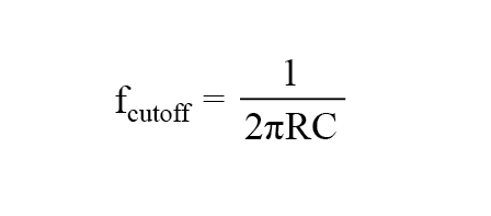
In the example circuit, there is no resistance other than the load resistor, so that is the value for R in the formula.
Application of High-Pass Filter
Using a stereo system as a practical example, a capacitor connected in series with the tweeter (treble) speaker will serve as a high-pass filter, imposing a high impedance to low-frequency bass signals, thereby preventing that power from being wasted on a speaker inefficient for reproducing such sounds.
In like fashion, an inductor connected in series with the woofer (bass) speaker will serve as a low-pass filter for the low frequencies that particular speaker is designed to reproduce.
In this simple example circuit, the midrange speaker is subjected to the full spectrum of frequencies from the stereo’s output. More elaborate filter networks are sometimes used, but this should give you the general idea.
Also bear in mind that I’m only showing you one channel (either left or right) on this stereo system. A real stereo would have six speakers: 2 woofers, 2 midranges, and 2 tweeters.
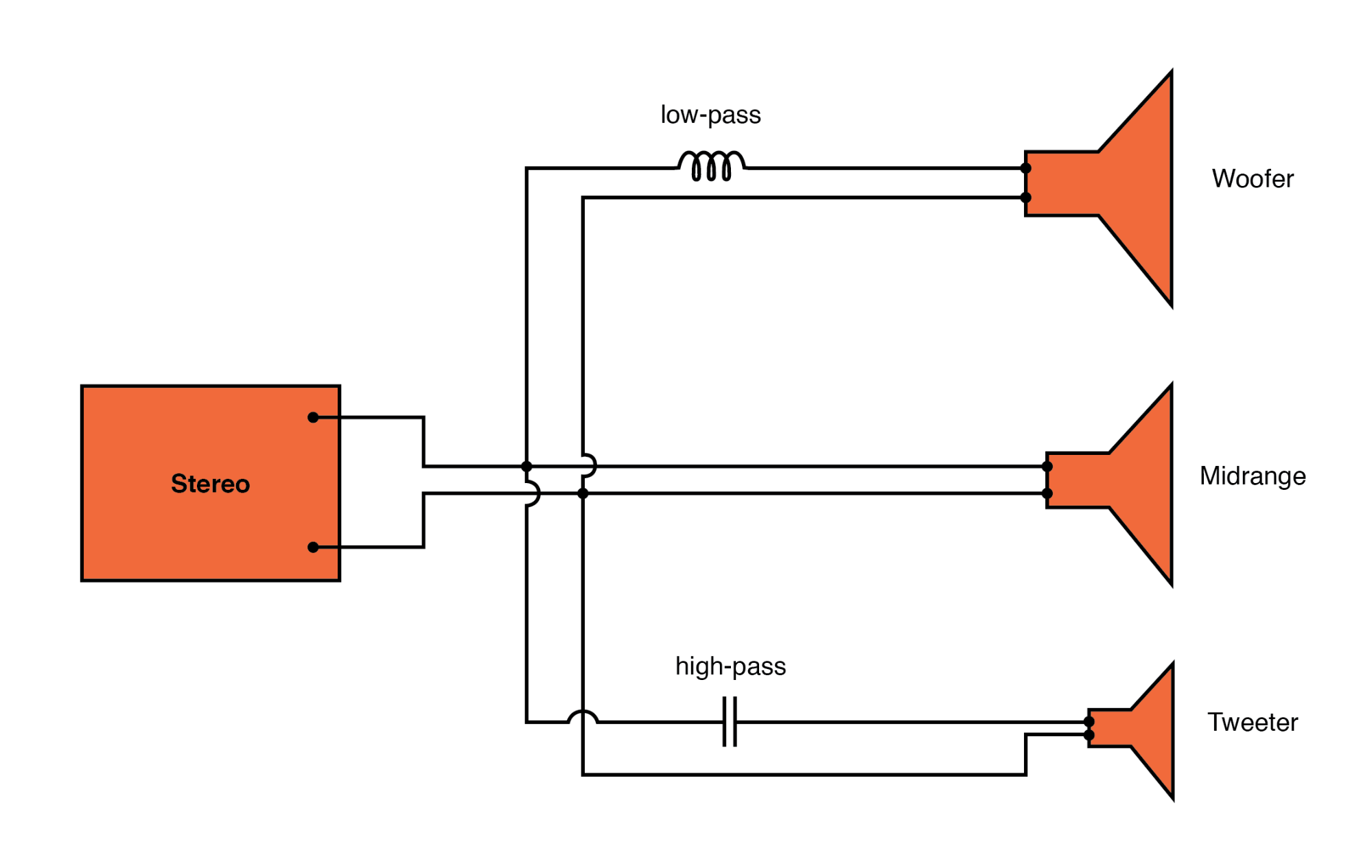
High-pass filter routes high frequencies to tweeter, while low-pass filter routes lows to woofer.
For better performance yet, we might like to have some kind of filter circuit capable of passing frequencies that are between low (bass) and high (treble) to the midrange speaker so that none of the low- or high-frequency signal power is wasted on a speaker incapable of efficiently reproducing those sounds.
What we would be looking for is called a band-pass filter, which is the topic of the next section.
REVIEW:
- A high-pass filter allows for easy passage of high-frequency signals from source to load, and difficult passage of low-frequency signals.
- Capacitive high-pass filters insert a capacitor in series with the load; inductive high-pass filters insert a resistor in series and an inductor in parallel with the load. The former filter design tries to “block” the unwanted frequency signal while the latter tries to short it out.
- The cutoff frequency for a high-pass filter is that frequency at which the output (load) voltage equals 70.7% of the input (source) voltage. Above the cutoff frequency, the output voltage is greater than 70.7% of the input, and vice versa.
RELATED WORKSHEETS: