Facebook
 Google
 GitHub
 Linkedin
Basic Electricity
Performance-Based Assessments for Basic Electricity Competencies
29 questions By Tony R. Kuphaldt
-
Question 19 of 29
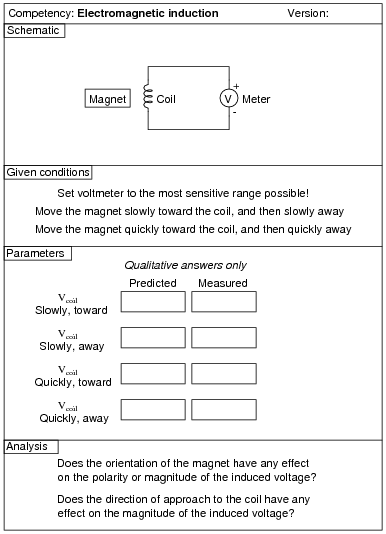
Reveal answerThe magnitude of the induced voltage is a direct function of the magnetic flux’s rate of change over time ([(d φ)/dt]).
Notes:Old solenoid valve coils work very well for this exercise, as do spools of wire with large steel bolts passed through the center. Students may also wind their own coils using small-gauge magnet wire and a steel bolt.
Please note that students will not be able to predict the polarity of the induced voltage unless they know the rotation of the coil windings and the polarity of their magnet. This will only be possible if the windings are exposed to view or if the students wind their own coils, and if the magnet has its poles labeled “North” and “South” (or if this is determined experimentally by using the magnet as a compass).
Use magnets that are as strong as possible, and that have their poles on the physical ends. This may seem like a strange request, but I’ve seen students bring some unusual magnets to class for this experiment, whose poles are not located on the ends. One type of magnet that works well is the so-called “cow magnet,” used by cattle ranchers to protect cows’ multiple stomachs from injury from ingestion of fence staples and other ferromagnetic objects. These are a few inches long, cylindrical in shape (so the cow can swallow it like a big pill), and quite strong.
If students are using analog multimeters to measure the coil’s induced voltage, be sure to keep the multimeter far away from the magnet. Analog meter movements are generally quite sensitive to external magnetic fields and may register falsely if positioned too close to a strong magnet.
-
Question 20 of 29
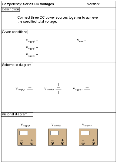
Reveal answerUse circuit simulation software to verify schematic diagram. Your real circuit will verify the pictorial diagram.
Notes:Use variable-voltage, regulated power supplies to supply any amount of DC voltage below 30 volts.
-
Question 21 of 29
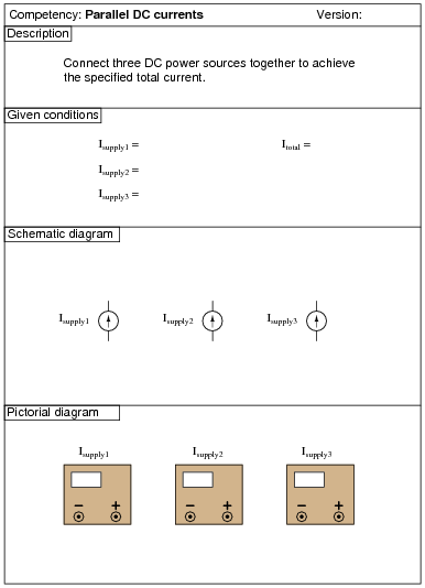
Caution! Consult your instructor to see how to set up each power supply to be a safe current source before attempting to connect them together!
Reveal answerUse circuit simulation software to verify schematic diagram. Your real circuit will verify the pictorial diagram.
Notes:Use regulated power supplies with adjustable current limits to act as current sources (voltage adjustments set to “full” while current adjustments set the desired output current for each). Keep the currents less than one amp for each supply.