Facebook
 Google
 GitHub
 Linkedin
Discrete Semiconductor Devices and Circuits
Performance-Based Assessments for Semiconductor Circuit Competencies
62 questions By Tony R. Kuphaldt
-
Question 55 of 62
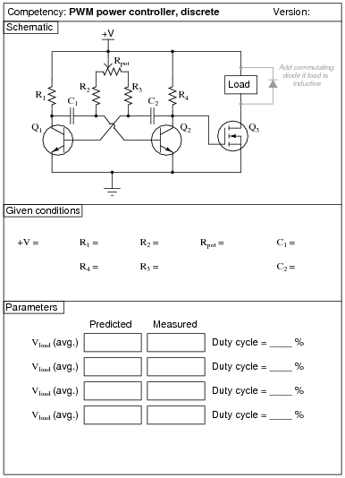
Reveal answerUse circuit simulation software to verify your predicted and measured parameter values.
Notes:Use a variable-voltage, regulated power supply to supply any amount of DC voltage below 30 volts. Specify standard resistor values, all between 1 kΩ and 100 kΩ (1k5, 2k2, 2k7, 3k3, 4k7, 5k1, 6k8, 10k, 22k, 33k, 39k 47k, 68k, etc.).
This circuit produces nice, sharp-edged square wave signals at the transistor collector terminals when resistors R1 and R4 are substantially smaller than the combined resistance of resistors R2 and R3 and the respective potentiometer section resistances. This way, Rpot, R2, and R3 dominate the capacitors’ charging times, making calculation of duty cycle much more accurate. Component values I’ve used with success are 1 kΩ for R1 and R4, 10 kΩ for R2 and R3, 100 kΩ for Rpot, and 0.001 μF for C1 and C2. In my prototype circuit, I used 2N2222 bipolar transistors and an IRF510 power MOSFET.
Although small DC motors work well as demonstrative loads, their counter-EMF may wreak havoc with measurements of average load voltage. Purely resistive loads work best when comparing measured average load voltage against predicted average load voltage. Also, motors and other inductive loads may cause the MOSFET to switch incorrectly (or not switch at all!) unless a commutating diode is installed to limit the voltage induced by the collapsing magnetic field every time the transistor turns off.
An extension of this exercise is to incorporate troubleshooting questions. Whether using this exercise as a performance assessment or simply as a concept-building lab, you might want to follow up your students’ results by asking them to predict the consequences of certain circuit faults.
-
Question 56 of 62

Reveal answerUse circuit simulation software to verify your predicted and measured parameter values.
Notes:Use a variable-voltage, regulated power supply to supply any amount of DC voltage below 30 volts. Specify standard resistor values, all between 1 kΩ and 100 kΩ (1k5, 2k2, 2k7, 3k3, 4k7, 5k1, 6k8, 10k, 22k, 33k, 39k 47k, 68k, etc.).
I have had relatively good success with the following values:
- VCC = 9 volts (from battery)
- C1 through C3 = 0.001 μF
- C4 and C5 = 4.7 μF
- R1 through R3 = 10 kΩ
- R4 = 270 kΩ
- R5 = 50 kΩ (two 100 kΩ resistors in parallel)
- R6 = 12 kΩ (you might want to make this resistor variable so students can experiment with AV)
- R7 = 1 kΩ
- Q1 = part number 2N3403
One of the problems with the RC phase-shift oscillator circuit design is the loading of the phase-shift network by the transistor’s biasing network (R4 and R5), which will offset the predicted oscillation frequency from what you might expect from the RC network alone. While it is possible to account for all the factors in this circuit, it is not a simple task for students just beginning to understand how the circuit is supposed to work.
I have also noticed that the frequency of this circuit is significantly reduced by the capacitance of any test leads connected to it. Beware of oscilloscope probe cables - the capacitance they add to the circuit will offset the oscillation frequency!
An extension of this exercise is to incorporate troubleshooting questions. Whether using this exercise as a performance assessment or simply as a concept-building lab, you might want to follow up your students’ results by asking them to predict the consequences of certain circuit faults.
-
Question 57 of 62

Reveal answerUse circuit simulation software to verify your predicted and measured parameter values.
Notes:I have had success with the following values:
- VCC = 12 to 24 volts
- C1 = 0.47 μF
- C2 = 0.47 μF
- T1 = 1000:8 Ω audio matching transformer (used as center-tap inductor)
- R1 = 1.5 MΩ
- Q1 = part number 2N3403
Capacitors C1 and C2 need not be equal value, since they serve entirely different purposes: C1 is the tank circuit capacitance, while C2 is merely a coupling capacitor. I just happened to be blessed with an abundance of 0.47 μF capacitors when I prototyped this circuit, so I chose that value for both capacitors!
With these component values, the output waveform I measured was not very sinusoidal, but at least it was oscillating. The harmonic output of a Hartley oscillator is substantially greater than a Colpitts, primary because the two capacitors in the Colpitts design act as decoupling capacitances, shunting high-order harmonic signals to ground.
Of course, in order to predict the frequency of oscillation in this Hartley oscillator circuit, you must know the inductance of the audio transformer’s primary winding!
You might want to quiz your students on the purpose of resistor R1, since it usually only has to be present at power-up to initiate oscillation!
An extension of this exercise is to incorporate troubleshooting questions. Whether using this exercise as a performance assessment or simply as a concept-building lab, you might want to follow up your students’ results by asking them to predict the consequences of certain circuit faults.