Facebook
 Google
 GitHub
 Linkedin
Analog Integrated Circuits
Phase-Locked Loops
8 questions By Tony R. Kuphaldt
-
Question 4 of 8
Suppose a technician connected a potentiometer to the input of a VCO, to act as a manually-variable voltage source. Then, the technician compares the output of the VCO with an external signal source that slowly changes frequency, adjusting the potentiometer to keep the two frequencies equal:

If a voltmeter were connected between the potentiometer wiper and ground, what would its indication represent (with regard to the external audio signal)?
Explain where feedback occurs in this system, and how the system may be automated so as to not require the continual attention of a technician.
Reveal answerThe wiper voltage in this system is representative of the external signal’s frequency. Feedback occurs in the “loop” formed by the technician’s hand, adjusting the potentiometer in response to changes in differential frequency.
Notes:Tell your students that voltage-controlled oscillators are sometimes called voltage-to-frequency converters. Then, ask them to explain how the presence of feedback in this system provides a frequency-to-voltage conversion function.
The question regarding automation of this system may be challenging for some of your students. If they cannot give a technical answer for this question, ask them to explain “in layman’s terms” what the additional components must do. Accurately identifying the function of a human operator is the first step in designing an automation system!
-
Question 5 of 8
A block diagram of a phase-locked loop circuit looks like this:

Determine what type of electronic signals would be seen at points A and B for the following input conditions:
- Input = sine wave, steady frequency
- Input = sine wave, increasing frequency
- Input = sine wave, decreasing frequency
- Input = sine wave, frequency increases and decreases regularly
Reveal answer- Input = sine wave, steady frequency
- - A: Steady DC voltage
- - B: frequency equal to input signal
- Input = sine wave, increasing frequency
- - A: Increasing DC voltage
- - B: frequency equal to input signal
- Input = sine wave, decreasing frequency
- - A: Decreasing DC voltage
- - B: frequency equal to input signal
- Input = sine wave, frequency increases and decreases regularly
- - A: DC voltage that rises and falls with input frequency
- - B: frequency equal to input signal
Notes:The purpose of this question is to get students to recognize the function of each “block” in a phase-locked loop. Having them predict the types of output signals at points A and B for different input signal conditions reveals whether or not they understand the concept.
Ask them where they obtained their information on phase-locked loop operation. I’ve seen quite a few tutorials on the internet for this subject, so there should be no problem with students finding sources.
-
Question 6 of 8
Suppose that a “noisy” AC signal of otherwise constant frequency is connected to the input of a phase-locked loop circuit:
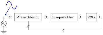
Characterize the output waveform generated by the VCO. Will it be “noisy” as well? Why or why not?
Reveal answerThe VCO’s output waveform will not be noisy like the input waveform.
Notes:Ask your students how this behavior of the PLL circuit could be advantageous. What practical purpose(s) can students think of for a PLL, used as such?