Facebook
 Google
 GitHub
 Linkedin
Analog Integrated Circuits
Phase-Locked Loops
8 questions By Tony R. Kuphaldt
-
Question 1 of 8
This is a schematic for a simple VCO:

The oscillator is of the RC “phase shift” design. Explain how this circuit works. Why does the output frequency vary as the control voltage varies? Does the output frequency increase or decrease as the control voltage input receives a more positive voltage?
Hint: the JFETs in this circuit are not functioning as amplifiers!
Reveal answerTo understand how the JFETs are functioning in this VCO design, closely examine the “saturation” regions of a JFET’s characteristic curves. Note that these regions appear as nearly straight-line sections. This indicates something about the behavior of a saturated JFET that is exploited in this VCO circuit.
The output frequency decreases as the control voltage becomes more positive.
Notes:Not only does this question allow students to examine the workings of a VCO, but it also provides a good review of JFET theory, as well as a practical example of a special application of junction field-effect transistors.
Note: the schematic diagram for this circuit was derived from one found on page 997 of John Markus’
Guidebook of Electronic Circuits, first edition. Apparently, the design originated from a Motorola publication on using field effect transistors (“Low Frequency Applications of Field-Effect Transistors,” AN-511, 1971).
-
Question 2 of 8
If you have ever heard the sound of a dual-engine airplane flying overhead, you probably noticed an unusual “beat” pattern to the engines’ tone. The same phenomenon happens when you play the output of two audio signal generators through speakers, with the signal generators set to very similar (but not identical!) frequencies:
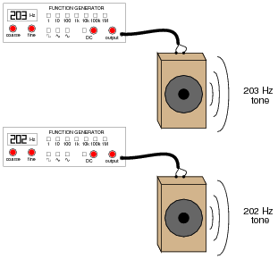
Explain how this phenomenon could be used by a technician to adjust two audio frequency sources to the same frequency, without the aid of any expensive test equipment such as a frequency counter or an oscilloscope.
Reveal answerAdjust the frequency of one of the sources until no “beating” sound is heard anymore between the two audio tones.
Notes:This is a very simple experiment to set up in the classroom, but beware! I once had two audio signal generators creating low-frequency sine-wave tones for my students, shortly after their lunch break. With full stomachs, a couple of my students had a very difficult time remaining awake while listening to the low tones.
-
Question 3 of 8
What is a VCO?
Reveal answerA VCO is a Voltage Controlled Oscillator.
Notes:Ask your students how a VCO might be used in a circuit. What, exactly, does “voltage controlled” mean?