Facebook
 Google
 GitHub
 Linkedin
AC Electric Circuits
Series and Parallel AC Circuits
75 questions By Tony R. Kuphaldt
-
Question 49 of 75
Determine the necessary resistor value to give the output voltage a phase shift of -64o:

Also, write an equation that solves for this resistance value (R), given all the other variables (f, C, and phase angle θ).
Reveal answerR = 16.734 kΩ
R = − tanθ 2 πf CNotes:Discuss with your students what a good procedure might be for calculating the unknown values in this problem, and also how they might check their work.
Students often have difficulty formulating a method of solution: determining what steps to take to get from the given conditions to a final answer. While it is helpful at first for you (the instructor) to show them, it is bad for you to show them too often, lest they stop thinking for themselves and merely follow your lead. A teaching technique I have found very helpful is to have students come up to the board (alone or in teams) in front of class to write their problem-solving strategies for all the others to see. They don’t have to actually do the math, but rather outline the steps they would take, in the order they would take them.
By having students
outline their problem-solving strategies, everyone gets an opportunity to see multiple methods of solution, and you (the instructor) get to see how (and if!) your students are thinking. An especially good point to emphasize in these “open thinking” activities is how to check your work to see if any mistakes were made.
-
Question 50 of 75
Calculate the total impedance offered by these two capacitors to a sinusoidal signal with a frequency of 3 kHz:

Show your work using two different problem-solving strategies:
- Calculating total capacitance (Ctotal) first, then total impedance (Ztotal).
- Calculating individual impedances first (ZC1 and ZC2), then total impedance (Ztotal).
Do these two strategies yield the same total impedance value? Why or why not?
Reveal answerFirst strategy:
Ctotal = 6.875 nF
Xtotal = 7.717 kΩ
Ztotal = 7.717 kΩ ∠−90o or Ztotal = 0 − j7.717 kΩ
Second strategy:
XC1 = 5.305 kΩ ZC1 = 5.305 kΩ ∠−90o
XC2 = 2.411 kΩ ZC1 = 2.411 kΩ ∠−90o
Ztotal = 7.717 kΩ ∠−90o or Ztotal = 0 − j7.717 kΩ
Notes:A common misconception many students have about capacitive reactances and impedances is that they must interact “oppositely” to how one would normally consider electrical opposition. That is, many students believe capacitive reactances and impedances should add in parallel and diminish in series, because that’s what capacitance (in Farads) does! This is not true, however. Impedances always add in series and diminish in parallel, at least from the perspective of complex numbers. This is one of the reasons I favor AC circuit calculations using complex numbers: because then students may conceptually treat impedance just like they treat DC resistance.
The purpose of this question is to get students to realize that any way they can calculate total impedance is correct, whether calculating total capacitance and then calculating impedance from that, or by calculating the impedance of each capacitor and then combining impedances to find a total impedance. This should be reassuring, because it means students have a way to check their work when analyzing circuits such as this!
-
Question 51 of 75
A student measures voltage drops in an AC circuit using three voltmeters and arrives at the following measurements:
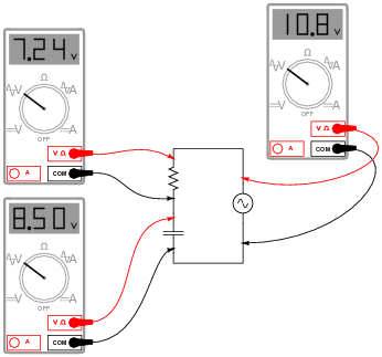
Upon viewing these measurements, the student becomes very perplexed. Aren’t voltage drops supposed to add in series, just as in DC circuits? Why, then, is the total voltage in this circuit only 10.8 volts and not 15.74 volts? How is it possible for the total voltage in an AC circuit to be substantially less than the simple sum of the components’ voltage drops?
Another student, trying to be helpful, suggests that the answer to this question might have something to do with RMS versus peak measurements. A third student disagrees, proposing instead that at least one of the meters is badly out of calibration and thus not reading correctly.
When you are asked for your thoughts on this problem, you realize that neither of the answers proposed thus far are correct. Explain the real reason for the “discrepancy” in voltage measurements, and also explain how you could experimentally disprove the other answers (RMS vs. peak, and bad calibration).
Reveal answerAC voltages still add in series, but phase must also be accounted for when doing so. Unfortunately, multimeters provide no indication of phase whatsoever, and thus do not provide us with all the information we need. (Note: just by looking at this circuit’s components, though, you should still be able to calculate the correct result for total voltage and validate the measurements.)
I’ll let you determine how to disprove the two incorrect explanations offered by the other students!
Challenge question: calculate a set of possible values for the capacitor and resistor that would generate these same voltage drops in a real circuit. Hint: you must also decide on a value of frequency for the power source.
Notes:This question has two different layers: first, how to reconcile the “strange” voltage readings with Kirchhoff’s Voltage Law; and second, how to experimentally validate the accuracy of the voltmeters and the fact that they are all registering the same type of voltage (RMS, peak, or otherwise, it doesn’t matter). The first layer of this question regards the basic concepts of AC phase, while the second exercises troubleshooting and critical thinking skills. Be sure to discuss both of these topics in class with your students.