
 Facebook
 Google
 GitHub
 Linkedin
Basic Electricity
Series DC Circuits Practice Worksheet with Answers
27 questions By Tony R. Kuphaldt
-
Question 25 of 27
Predict how all test point voltages (measured between each test point and ground) in this circuit will be affected as a result of the following faults. Consider each fault independently (i.e. one at a time, no multiple faults):

- • Resistor R1 fails open:
- • Resistor R2 fails open:
- • Resistor R3 fails open:
- • Solder bridge (short) past resistor R2:
For each of these conditions, explain why the resulting effects will occur.
Reveal answer- • Resistor R1 fails open: VTP1 = no change (source voltage), VTP2 = decrease to 0 volts, VTP3 = decrease to 0 volts.
- • Resistor R2 fails open: VTP1 = no change (source voltage), VTP2 = increase to full source voltage, VTP3 = decrease to 0 volts.
- • Resistor R3 fails open: VTP1 = no change (source voltage), VTP2 = increase to full source voltage, VTP3 = increase to full source voltage.
- • Solder bridge (short) past resistor R2: VTP1 = no change (source voltage), VTP2 = decrease, VTP3 = increase, VTP2 = VTP3.
Notes:The purpose of this question is to approach the domain of circuit troubleshooting from a perspective of knowing what the fault is, rather than only knowing what the symptoms are. Although this is not necessarily a realistic perspective, it helps students build the foundational knowledge necessary to diagnose a faulted circuit from empirical data. Questions such as this should be followed (eventually) by other questions asking students to identify likely faults based on measurements.
-
Question 26 of 27
A student is troubleshooting a two-resistor voltage divider circuit, using a table to keep track of his test measurements and conclusions. The table lists all components and wires in the circuit so that the student may document their known status with each successive measurement:
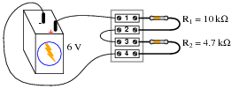
Measurement taken Battery Wire /1 R1 Wire 2/3 R2 Wire 4/-
Prior to beginning troubleshooting, the student is told there is no voltage across R2. Thus, the very first entry into the table looks like this:
Measurement taken Battery Wire /1 R1 Wire 2/3 R2 Wire 4/-
VR2 = 0 V
Based on this data, the student then determines possible faults which could cause this to happen, marking each possibility in the table using letters as symbols. The assumption here is that there is only one fault in the circuit, and that it is either a complete break (open) or a direct short:
Measurement taken Battery Wire /1 R1 Wire 2/3 R2 Wire 4/-
VR2 = 0 V O O O O S O
“O” symbolizes a possible “open” fault, while “S” symbolizes a possible “shorted” fault.Next, the student measures between terminals 1 and 4, obtaining a full 6 volt reading. This is documented on the table as well, along with some updated conclusions regarding the status of all wires and components:
Measurement taken Battery Wire /1 R1 Wire 2/3 R2 Wire 4/-
VR2 = 0 V O O O O S O
V1−4 = 6 V OK OK O O S OK
After this, the student measures between terminals 1 and 2 (across resistor R1), and gets a reading of 0 volts. Complete the table based on this last piece of data:
Measurement taken Battery Wire /1 R1 Wire 2/3 R2 Wire 4/-
VR2 = 0 V O O O O S O
V1−4 = 6 V OK OK O O S OK
VR1 = 0 V
Reveal answer
Measurement taken Battery Wire /1 R1 Wire 2/3 R2 Wire 4/-
VR2 = 0 V O O O O S O
V1−4 = 6 V OK OK O O S OK
VR1 = 0 V OK OK OK O OK OK
Conclusion: there is an open fault (break) between terminals 2 and 3. This is the only single fault which will account for all the data.Notes:The main purpose of this question is to introduce students to this style of documentation and strategy for use in troubleshooting a circuit. For each successive reading, the student is required to re-assess the status of each component, figuring out what single failure could account for all data up to that point.
-
Question 27 of 27
This voltage divider circuit has a problem: there is no voltage output between terminals 7 and 8.
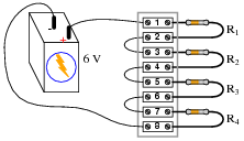
A technician has taken several measurements with a voltmeter, documenting them chronologically from top to bottom in the far-left column:
Measurement Batt ( )/1 R1 2/3 R2 4/5 R3 6/7 R4 8/(-)
V1−8 = 6 V
V1−5 = 0 V
V5−7 = 6 V
Fill in all cells of this table with one of three different symbols, representing the status of each component or wire (numbers separated by a slash indicate the wire connecting those terminals):- • O for an “open” fault
- • S for an “short” fault
- • OK for no fault
You are to assume that there is only one fault in this circuit, and that it is either a complete break (open) or a direct short (zero resistance). After completing the table, assess whether or not the exact fault may be known from the data recorded thus far. If not, suggest the next logical voltage measurement to take.
Reveal answer
Measurement Batt ( )/1 R1 2/3 R2 4/5 R3 6/7 R4 8/(-)
V1−8 = 6 V OK OK O O O O O O S OK
V1−5 = 0 V OK OK OK OK OK OK O O S OK
V5−7 = 6 V OK OK OK OK OK OK O O OK OK
We do not yet have enough information to determine whether resistor R3 or wire 6/7 is failed open. A good voltage measurement to take now would be across the resistor (terminals 5 and 6), or between terminals 6 and 7.Follow-up question: describe how much voltage you would expect to find between either of these terminal pairs, given an open fault with either suspected component.
Notes:Ask your students to defend their answers for each component status, for each of the successive measurements. What you will find is that this forces students to rigorously analyze the possibilities of a fault in each portion of the circuit. Not only is this beneficial for reinforcing basic circuit principles, but it also teaches students to consider all possibilities when troubleshooting a circuit.






llaboutcircuits.com/worksheets/series-dc-circuits/. In question 5, total series resistance is sum of each resistor, not product. Correct both question and answer
Hello Everybody and thanks for your fantastic articles!
I’m having troubles solving Excercise 19 of your Series circuits problems (https://www.allaboutcircuits.com/worksheets/series-dc-circuits/): For this excercise I’m getting a power dissipation for the heater of 403 W instead of 321.1 W.
Since I’m learning electronics I’m surely doing something wrong… Here how I’m reasoning:
1. With 110 V and a power dissipated of 500 W, I can calculate the current in the circuit, that should be I=P/V 500/110 = 4.545 A
2. Knowing that the current in the circuit is 4.545 A I can use Ohm’s law to calculate the resistance of the heater: R=V/I 110/4.545 = 24 Ohm
3. Now, longing the wires it’s the same as adding 6 Ohm of resistance, for a total resistance of 30 Ohm (24 + 6) so the current in the circuit will change accordingly. To find the new amount of current I use Ohm’s law once again: I=V/R 110/30 = 3.666 A
4. Having a new current value of 3.666 A, I can now calculate power dissipation P=V*I 110*3.666 = 403 W
Could you please help me understand where I’m wrong?
Thank you so much!
Stefano.