Facebook
 Google
 GitHub
 Linkedin
Discrete Semiconductor Devices and Circuits
Thyristor Application Circuits
16 questions By Tony R. Kuphaldt
-
Question 16 of 16
The following schematic diagram shows a timer circuit made from a UJT and an SCR:
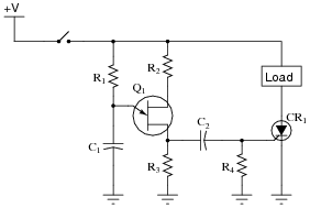
Together, the combination of R1, C1, R2, R3, and Q1 form a relaxation oscillator, which outputs a square wave signal. Explain how a square wave oscillation is able to perform a simple time-delay for the load, where the load energizes a certain time after the toggle switch is closed. Also explain the purpose of the RC network formed by C2 and R4.
Reveal answerRemember that CR1 only needs one pulse at its gate to turn (and latch) it on! C2 and R4 form a passive differentiator to condition the square wave signal from the UJT oscillator.
Follow-up question: how would you suggest we modify this circuit to make the time delay adjustable?
Notes:Knowing that the UJT forms an oscillator, it is tempting to think that the load will turn on and off repeatedly. The first sentence in the answer explains why this will not happen, though.
I got the basic idea for this circuit from the second edition of
Electronics for Industrial Electricians, by Stephen L. Herman.