
 Facebook
 Google
 GitHub
 Linkedin
DC Electric Circuits
Time Constant Calculations
52 questions By Tony R. Kuphaldt
-
Question 7 of 52
The following circuit allows a capacitor to be rapidly charged and slowly discharged:

Suppose that the switch was left in the “charge” position for some substantial amount of time. Then, someone moves the switch to the “discharge” position to let the capacitor discharge. Calculate the amount of capacitor voltage and capacitor current at exactly 3 seconds after moving the switch to the “discharge” position.
VC =
@ t = 3 seconds
IC =
@ t = 3 seconds
Also, show the direction of discharge current in this circuit.
Reveal answerVC = 1.9915 volts
@ t = 3 seconds
IC =
995.74 μA @ t = 3 seconds

Notes:Here, students must choose which equation(s) to use for the calculation, calculate the time constant for the circuit, and put all the variables in the right place to obtain the correct answers. Discuss all these steps with your students, allowing them to explain how they approached the question.
If anyone asks, let them know that the capacitor symbol shown represents a polarized (electrolytic) capacitor.
-
Question 8 of 52
The following circuit allows a capacitor to be rapidly discharged and slowly charged:

Suppose that the switch was left in the “discharge” position for some substantial amount of time. Then, someone moves the switch to the “charge” position to let the capacitor charge. Calculate the amount of capacitor voltage and capacitor current at exactly 45 milliseconds after moving the switch to the “charge” position.
VC =
@ t = 45 ms
IC =
@ t = 45 ms
Reveal answerVC = -13.08 volts
@ t = 45 ms
IC =
236.6 μA @ t = 45 ms
Follow-up question: show the directions of charge and discharge current in this circuit.
Notes:Here, students must choose which equation(s) to use for the calculation, calculate the time constant for the circuit, and put all the variables in the right place to obtain the correct answers. Discuss all these steps with your students, allowing them to explain how they approached the question.
If anyone asks, let them know that the capacitor symbol shown represents a polarized (electrolytic) capacitor.
-
Question 9 of 52
Qualitatively determine the voltages across all components as well as the current through all components in this simple RC circuit at three different times: (1) just before the switch closes, (2) at the instant the switch contacts touch, and (3) after the switch has been closed for a long time. Assume that the capacitor begins in a completely discharged state:
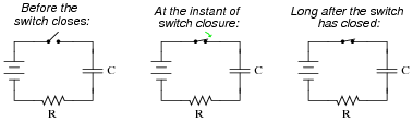
Express your answers qualitatively: “maximum,” “minimum,” or perhaps “zero” if you know that to be the case.
Before the switch closes:
VC =
VR =
Vswitch =
I =
At the instant of switch closure:
VC =
VR =
Vswitch =
I =
Long after the switch has closed:
VC =
VR =
Vswitch =
I =
Hint: a graph may be a helpful tool for determining the answers!
Reveal answerBefore the switch closes:
VC = zero
VR = zero
Vswitch = maximum
I = zero
At the instant of switch closure:
VC = zero
VR = maximum
Vswitch = zero
I = maximum
Long after the switch has closed:
VC = maximum
VR = zero
Vswitch = zero
I = zero
Follow-up question: which of these variables remained the same immediately before and immediately after switch closure? Explain why.
Notes:The purpose of this question is to preview the concept of “initial” and “final” values in RC circuits, before they learn to use the “universal time constant formula.”





Maybe this will help someone else. The general formulas for V(t) and I(t) in question 25 (and the x(t) versions in question s 23 and 14) contain typos (or maybe hypertext coding glitches). They should actually be V(t) = (Vf-Vo)(1-e^(-t/𝛕)) + Vo, I(t) = (If-Io)(1-e^(-t/𝛕)) + Io in question 25. Those are correct in the PDF download version. In questions 23 and 24 the equations are x = xinitial + ( xfinal − xinitial ) ( 1 − e[(−t)/(τ)] ).