Facebook
 Google
 GitHub
 Linkedin
Digital Circuits
Time-Delay Electromechanical Relays
19 questions By Tony R. Kuphaldt
-
Question 13 of 19
Suppose an engineer draws the following timing diagram for a time-delay relay circuit and then hands the diagram to a technician to figure out how to build it:

The technician, being well educated in the ways of time-delay relays, takes one look at this timing diagram and begins to laugh. Explain why this diagram is funny.
Reveal answerTime-delay relays can do a lot of neat things, but they cannot predict the future!
Notes:The real purpose of this question is to get students to recognize an impossibility in timing diagrams. As an instructor, I see students mistakes such as this once in a while. Those students who have trouble answering this question may not yet fully understand how to interpret timing diagrams!
-
Question 14 of 19
Determine what sort of time-delay relay this circuit is:
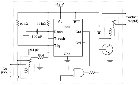
Also, calculate the amount of delay, in seconds. Hint: the 555’s timing capacitor will charge from 0 volts to 2/3 supply voltage during the charging cycle.
Reveal answerThis is a normally-open, timed-closed (also known as a normally-open, on-delay) relay, with a time delay of 4.065 seconds.
Notes:Some students may mistakenly base their time calculations on the 10 kΩ resistor and/or the 0.1 μF capacitor. Discuss the role of these two components in triggering the 555 timer, and how the time delay of the relay is actually set by the other R and C.
-
Question 15 of 19
Explain what a time-delay relay is, and how it functionally differs from a regular electromechanical relay.
Reveal answerA “time-delay” relay either waits before actuating after power-up, or waits before de-actuating after power-down.
Notes:The earliest time-delay relays used pneumatic “dash-pot” motion dampers to provide the necessary actuation or de-actuation delays. Modern time-delay relays use electronic timer circuits to do the time delay function, even when the output of the relay is still a set of mechanical contacts.