Facebook
 Google
 GitHub
 Linkedin
Volume
EE Reference
Chapter
Circuit Schematic Symbols
Switches, Electrically Actuated (Relays)
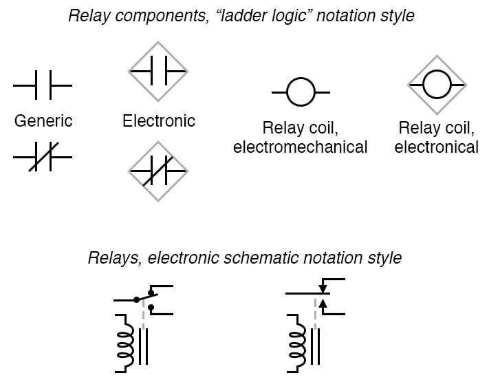
The structure behind ladder logic is based on the electrical ladder diagrams that were used with relay logic.
These diagrams documented how connections between devices were made on relay panels; they are called “ladder” diagrams because they are constructed in a way that resembles a ladder with two vertical rails and rungs between them.
RELATED WORKSHEETS:
Published under the terms and conditions of the Design Science License