Facebook
 Google
 GitHub
 Linkedin
Adding a Capacitive Touch Display Module to the BeagleBone Black
Pair a BeagleBone Black with a capacitive touch LCD display to create a development platform for small, cost-effective solutions.
Developers and engineers who want to create intuitive interfaces for industrial and home automation often look for LCD displays with minimal button interaction. Capacitive displays remove the necessity of any buttons while maintaining interactivity. On top of that, it's often necessary to login or update systems remotely. The BeagleBone paired with a capacitive touch LCD display is a development platform for small, cost-effective solutions.
The BeagleBone Black is a low-cost, community-supported development platform. The BeagleBone boards are designed as open source alternatives to other development platforms, allowing the designer or engineer to commence development with the BeagleBone and progress onto their own custom systems using the same hardware. All of the schematics, layout files, and bill of materials are freely available.
The board is based around the Texas Instruments Sitara AM335x system on chip Cortex A8 ARM processor. The processor core runs at 1 GHz, has a PowerVR SGX 530 graphics core and is connected up to 512 MB of low-power DDR3L memory clocked at 400 MHz. Peripherals include up to 65 GPIOs, a single USB 2.0 port, 10/100 Ethernet jack, a microSD slot for storage and a mini HDMI connector.
The BeagleBones use stackable daughterboards called 'capes' to attach a wide variety of community-based development boards adding functionality ranging from LCD displays and motor drivers to cellular modems and GPS/GPRS modules. An example of a range of LCD displays designed specifically for the BeagleBone Black is that of the GEN4 series manufactured by 4D Systems. Their range includes 4.3, 5.0, or 7.0-inch primary displays for direct user interaction and information display.
These displays are available in both resistive touch (GEN4-4DCAPE-xxT), capacitive touch (GEN4-4DCAPE-xxCT) and non-touch (GEN4-4DCAPE-xx), where xx is 43, 50 and 70. An optional external button board is available for actions such as up, down, left, right, enter/return, power and reset or as required by the user.
The capacitive touch display comes with a professional looking cover lens bezel, which is a glass front with overhanging edges, allowing the display to be mounted directly into a panel using special adhesive on the overhanging glass.
Getting Started
To get up and going with the BeagleBone Black with the 4D Systems LCD Cape, the following items are needed:
- BeagleBone Black
- 4D Systems 4.3" LCD Displays
- 4D Systems 4.3" Cape Adaptor
- 4GB MicroSD card
- USB to micro SD card adaptor
- 5 V, 2 A power supply
- Mini USB to USB cable
- Wireless keyboard and mouse combo (optional)
- RJ45 Ethernet cable (optional)
One of the appealing features of the BeagleBone is the gamut of options for interfacing with the device. Using only a mini USB cable, the user can power the board and use a serial interface like Putty.exe or Terraterm to login to the command line. The default username is 'debian' and the password is 'temppwd'.
Alternatively, the BeagleBone will register as a USB device on the host machine, once the correct USB-Network drivers have been installed, the user can then login to the BeagleBone through the web server interface running on the board (Chrome or Firefox, Internet Explorer is not supported) at http://192/168.7.2 - see Figure 1. In this web server interface, it is possible to write scripts in BoneScript in the Cloud9 IDE, which is a Node.js library optimized for the Beagle family using familiar Arduino function calls.

Figure 1. Web server interface running on BeagleBone Black.
Focusing on using the 4D Systems LCD Cape with the power off, connect the 4D cape adaptor to the BeagleBone Black. Be wary of the correct orientation and not to bend any of the pins as this can damage the cape. Then attach either end of the supplied 30 way FFC cable to the 4DCAPE display. The exposed metal should point upwards and the blue stiffener should face the PCB as in Figure 2.

Figure 2. BeagleBone Black 4DCape Adaptor for LCD Display.
Connect the other side the FFC cable to the adaptor board, ensuring the exposed metal pads facing upwards again as in Figure 3. If attaching any other capes, ensure there are no pin conflicts by checking the BeagleBone schematics. In Figure 3, an EEPROM can be seen on the back of LCD Cape that has a selectable I2C adress via DIP switch. This can be used to resolve I2C address conflicts with any other attached I2C devices.

Figure 3. Back of 4.3" 4D Systems LCD Display.
The BeagleBone comes loaded with Debian 3.8.13 on the on board 4GB eMMC NAND Flash, which unfortunately does not contain the correct drivers or overlays for this display. It is possible to update the Linux distribution, but it takes a little bit longer. The fastest way to get up and going is to walk through this tutorial to load the latest version of Debian to a 4GB microSD card (4.4.54 at time of writing). The download of the Debian Linux distribution could take 30 minutes or more and writing to the micro SD should take another 20 minutes to complete. Other Linux distributions like Angstrom and Android also support the 4DCAPE, but involve more work to get up and going.
Insert the microSD card into the holder on the bottom side of the BeagleBone, while the power is off. Hold down the BOOT button – see Figure 4 - and insert the 5 VDC plug. The BOOT button is a little difficult to access with the 4DCAPE attached, but a small screwdriver should reach. The 4DCAPE draws significant current (typical 620 mA for the GEN4-4DCAPE-43CT), which is far more than any USB port can handle, hence why a 5 V / 2 A external power supply is necessary. The USB jack will not supply power to the 4D Cape unless the solder bridge jumper on the top of the 4DCAPE adaptor board is cut and resoldered.

Figure 4. BeagleBone Black peripheral and button locations.
After a minute or two, the screen should flash white, then a flashing cursor up in the top right can be seen. Plug in the mini USB cable to the BeagleBone while it is powered and the other end to your computer. Start a serial session using Putty.exe or Terraterm with the following settings: 115200, 8, N, 1. The default username is 'debian' and the password is 'temppwd'. Note at this point with the LCD display attached, it is not possible to access the web server interface.
Enabling the Graphical Interface
The capacitive touch screen doesn't work in command line, so it makes sense to use the graphical interface. In order to activate the graphical interface, some small modifcations need to be made to the /boot/uEnv.txt file. Vi, Vim and Nano are all Linux command line text editors that can be used to edit this file. Check out this beginner's guide to the command line text editor, Nano.
The following command will open the file to be edited:
sudo nano /boot/uEnv.txtBefore editing any files, it is recommended to create a backup of the file first. This can be done using the following command;
sudo cp /boot/uEnv.txt /boot/uEnv-Backup.txtFind the following lines in the uEnv.txt file and change them to the following. This disables the HDMI interface, which conflicts with some of the pins to the LCD cape.
##Beaglebone Black/Green dtb's for v4.1.x (BeagleBone White just works..)

##Beaglebone Black: HDMI (Audio/Video) disabled:
dtb=am335x-boneblack-emmc-overlay.dtb

##Beaglebone Black: eMMC disabled:
dtb=am335x-boneblack-hdmi-overlay.dtb

##Beaglebone Black: HDMI Audio/eMMC disabled:
dtb=am335x-boneblack-nhdmi-overlay.dtb

##Beaglebone Black: HDMI (Audio/Video)/eMMC disabled:
dtb=am335x-boneblack-overlay.dtb

##Beaglebone Black: wl1835
#dtb=am335x-boneblack-wl1835mod.dtb

##Beaglebone Black: replicape
#dtb=am335x-boneblack-replicape.dtb

##Beaglebone Green: eMMC disabled
dtb=am335x-bonegreen-overlay.dtb
Once the changes have been made, save the file and reboot; shutdown -r now
This can take up to a few minutes to restart. Alternatively press the reset button on the board.
The screen should now boot into the graphical interface Openbox. It is useful to have a keyboard and a mouse to fully interact with the interface, but it is not completely necessary. There is only one USB 2.0 port available, so either a wireless keyboard and mouse combo or a USB hub can be used.
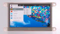
Attach an ethernet cable to a DHCP enabled network router and internet access can be obtained through Qupzilla or Chromium. Figure 5 shows the Qupzilla web browser working on the 4.3" LCD Display.

Figure 5. Qupzilla web browser running on 4.3" 4D Systems LCD display.
Due to the size of the screen, some of the programs only show part of the window.
Conclusion
Setting up the BeagleBone Black and 4D Systems LCD Cape is straightforward enough, which means the user can get developing as soon as possible. It is handy that the display overlays are available in the latest BeagleBone Debian distribution. The total setup time should take less than 90 minutes in total including download times. Once up and running, numerous options are available through the Openbox window manager.
Related Content