 Facebook
 Google
 GitHub
 Linkedin
Interface a Seven Segment Display to an Arduino
For many applications, there's no need to use a more expensive liquid crystal display to display data. A simple seven-segment display is sufficient.
For many applications, there's no need to use a more expensive liquid crystal display to display data. A simple seven-segment display is sufficient.
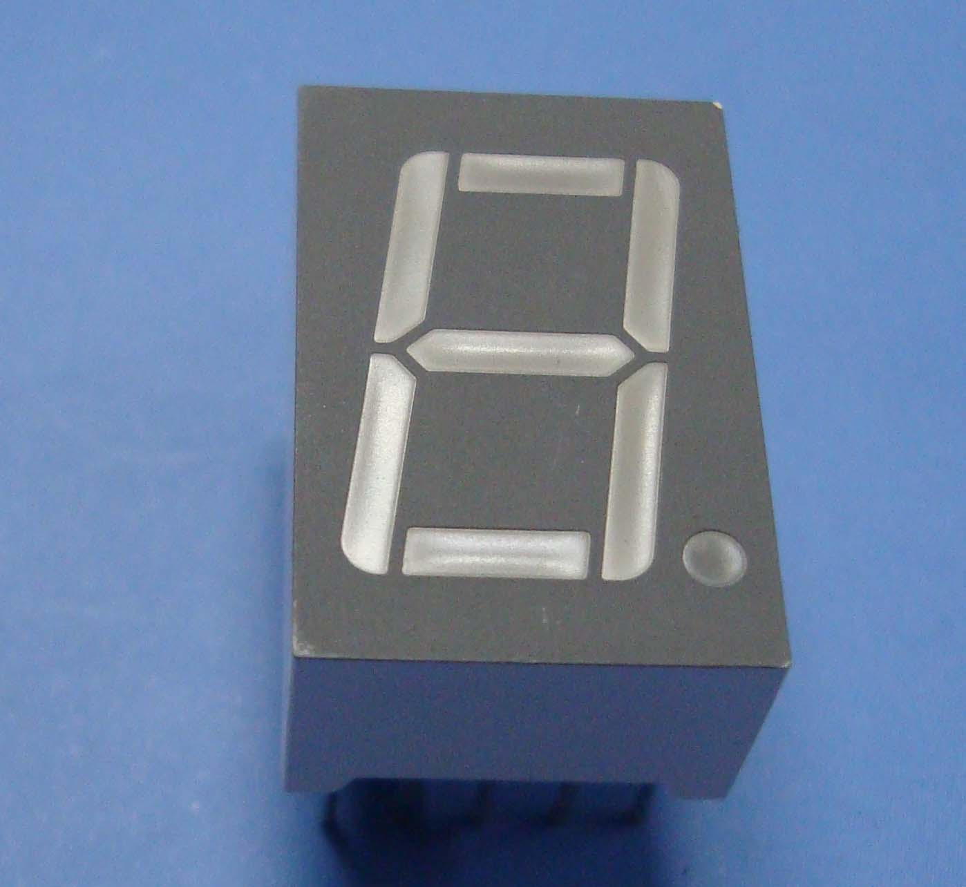
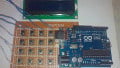
If your Arduino application only needs to display numbers, consider using a seven-segment display. The severn-segment display has seven LEDs arranged in the shape of number eight. They are easy to use and cost effective. The picture below shows a typical seven-segment display.
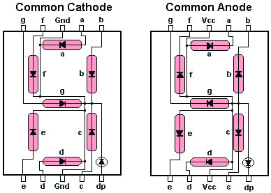
Seven segment displays are of two types: common anode and common cathode. The Internal structure of both types is nearly the same. The difference is the polarity of the LEDs and common terminal. In a common cathode seven-segment display (the one we used in the experiments), all seven LEDs plus a dot LED have the cathodes connected to pins 3 and pin 8. To use this display, we need to connect GROUND to pin 3 and pin 8 and, and connect +5V to the other pins to make the individual segments light up. The following diagram shows the internal structure of common-cathode seven-segment display:

Common Cathode
The common anode display is the exact opposite. In a common-anode display, the positive terminal of all the eight LEDs are connected together and then connected to pin 3 and pin 8. To turn on an individual segment, you ground one of the pins. The following diagram shows the internal structure of the common-anode seven-segment display.

Common anode
The seven segment are labelled a-g, with the dot being "dp," as shown in the figure below:
SSD Configuration
To display a particular number, you turn on the individual segments as shown in the table below:
|
Digit gfedcba |
abcdefg |
a |
b |
c |
d |
e |
f |
g |
|
|
0 0×3F |
0×7E |
on |
on |
on |
on |
on |
on |
off |
|
|
1 0×06 |
0×30 |
off |
on |
on |
off |
off |
off |
off |
|
|
2 0×5B |
0×6D |
on |
on |
off |
on |
on |
off |
on |
|
|
3 0×4F |
0×79 |
on |
on |
on |
on |
off |
off |
on |
|
|
4 0×66 |
0×33 |
off |
on |
on |
off |
off |
on |
on |
|
|
5 0×6D |
0×5B |
on |
off |
on |
on |
off |
on |
on |
|
|
6 0×7D |
0×5F |
on |
off |
on |
on |
on |
on |
on |
|
|
7 0×07 |
0×70 |
on |
on |
on |
off |
off |
off |
off |
|
|
8 0×7F |
0×7F |
on |
on |
on |
on |
on |
on |
on |
|
|
9 0×6F |
0×7B |
on |
on |
on |
on |
off |
on |
on |
|
|
A 0×77 |
0×77 |
on |
on |
on |
off |
on |
on |
on |
|
|
B 0×7C |
0×1F |
off |
off |
on |
on |
on |
on |
on |
|
|
C 0×39 |
0×4E |
on |
off |
off |
on |
on |
on |
off |
|
|
D 0×5E |
0×3D |
off |
on |
on |
on |
on |
off |
on |
|
|
E 0×79 |
0×4F |
on |
off |
off |
on |
on |
on |
on |
|
|
F 0×71 |
0×47 |
on |
off |
off |
off |
on |
on |
on |
|
Experiment 1
In this experiment, we will simply turn on and turn off the LEDs to get familiar with how a seven-segment display works.
Hardware Required
- 1 x seven segment display (common cathode)
- 1 x Arduino MEGA 2560
- 1 x breadboard
- 7 x 220 ohm resistors (1/4 W)
- jumper wires
Wiring Diagram
In this circuit, the pins of seven-segment display are connected to Arduino pins 2-9, as shown in the table below. Common pins (pin 3 and pin 8) are connected to GND and dp is left unconnected, because it is not used in this experiment
| Seven segment pins | Arduino pins | Wire Color |
|---|---|---|
| 1(e) | 6 | orange |
| 2(d) | 5 | white |
| 3,8(COM) | GND | n/a |
| c | 4 | yellow |
| 5(dp) | - | |
| 6(b) | 3 | red |
| 7(a) | 2 | blue |
| 9(f) | 7 | cyan |
| 10(g) | 8 | green |

Code
void setup()
{
  // define pin modes

 pinMode(2,OUTPUT);
 pinMode(3,OUTPUT);
 pinMode(4,OUTPUT);
 pinMode(5,OUTPUT);
 pinMode(6,OUTPUT);
 pinMode(7,OUTPUT);
 pinMode(8,OUTPUT);

}

void loop()
{
  // loop to turn leds od seven seg ON

  for(int i=2;i<9;i++)
  {
    digitalWrite(i,HIGH);
    delay(600);
  }

  // loop to turn leds od seven seg OFF
  for(int i=2;i<9;i++)
  {
    digitalWrite(i,LOW);
    delay(600);
  }


  delay(1000);

}
Experiment 2
Description
In this tutorial, we will be interfacing a seven segment display with Arduino mega and learn to display a count down from nine with a delay of a second, on seven segment display.
Hardware Required
The hardware required for this experiment is the same as for Experiment 1.
Wiring Diagram
The wiring diagram for this experiment is the same as the circuit for Experiment 1.
Code
// make an array to save Sev Seg pin configuration of numbers

int num_array[10][7] = {  { 1,1,1,1,1,1,0 },    // 0
                          { 0,1,1,0,0,0,0 },    // 1
                          { 1,1,0,1,1,0,1 },    // 2
                          { 1,1,1,1,0,0,1 },    // 3
                          { 0,1,1,0,0,1,1 },    // 4
                          { 1,0,1,1,0,1,1 },    // 5
                          { 1,0,1,1,1,1,1 },    // 6
                          { 1,1,1,0,0,0,0 },    // 7
                          { 1,1,1,1,1,1,1 },    // 8
                          { 1,1,1,0,0,1,1 }};   // 9

//function header
void Num_Write(int);

void setup()
{
  // set pin modes
  pinMode(2, OUTPUT);
  pinMode(3, OUTPUT);
  pinMode(4, OUTPUT);
  pinMode(5, OUTPUT);
  pinMode(6, OUTPUT);
  pinMode(7, OUTPUT);
  pinMode(8, OUTPUT);


}

void loop()
{

  //counter loop

  for (int counter = 10; counter > 0; --counter)
  {
   delay(1000);
   Num_Write(counter-1);
  }
  delay(3000);
}

// this functions writes values to the sev seg pins
void Num_Write(int number)
{
  int pin= 2;
  for (int j=0; j < 7; j++) {
   digitalWrite(pin, num_array[number][j]);
   pin++;
  }
}
aac_interface_a_seven_segment.zip
Video
Give this project a try for yourself! Get the BOM.


I’ve just started with Arduino so I’m sticking to yet simple projects ..similarly, I’ll try it with 2x 7-seg display from old PC casing so I wanted to try it in similar way (+ A..F) for hexadecimal digits.
From schematic It’s clear that your’e using 7-seg LED with common anode and since 7 of Arduino’s pins are used as ‘GND’, shouldn’t digitalWrite() function should be set LOW to power LED ON / HIGH to power it OFF (since it’s sinking current through the digital pins)?
The circuit drawn here is for common anode. I’m new to this stuf so it took me all day to figure this out. Also, the last two digits in the num_array are swapped. You won’t get to know this except in 3,2,1. The code looks fine, but I guess there is something with the data sheet. It was okay for me when I exchanged the two. But just a tip in case somebody is stuck like me. 😊