 Facebook
 Google
 GitHub
 Linkedin
Designing Smart Meters with Circuit Protection, Sensing, and Power Control Capabilities
This article offers an overview of the various component options for smart meter design and how they can improve the operation of the meters into which they are designed.
This article offers an overview of the various component options for smart meter design and how they can improve the operation of the meters into which they are designed.
Utility meters―once hidden away in cobwebby basements and behind shrubbery―are now emerging as leading players in energy conservation efforts. The latest generation of “smart” electricity, water, and gas meters now offer both commercial and residential customers the information they need to use these resources more wisely. They also allow utility companies to monitor usage remotely, largely eliminating the need for manual readings; they can even make it possible to smooth grid power peaks spot tampering, leakage, excess temperatures, etc.
The switch from traditional electromechanical meters to smart meters presents a variety of challenges for meter designers as they strive to develop solutions that are compatible with Advanced Metering Infrastructure (AMI). This allows integrating smart meters into the fast-growing Internet of Things (IoT), which supports remote communication and fault detection. However, one thing that has remained the same is that the utility companies that install these meters need them to be robust enough to operate reliably for decades and provide accurate measurements over the course of their lifetimes. To do that, they must incorporate a growing array of circuit protection, sensing, and power control components.
Circuit Protection Components
The sophisticated electronics in today’s smart meters require even greater protection from electrical transients (ESD), power surges (such as overcurrents like lightning spikes) and other occurrences than in the past. Figure 1 is a high-level block diagram of the subsystems within a typical residential electricity meter. Figure 2 illustrates the multiple functional blocks that gas and water meters have in common.

Figure 1. Smart electricity meter subsystems.
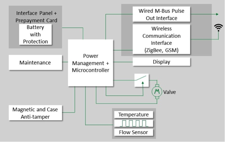
Figure 2. Smart gas and water meter subsystems.
Electricity meters draw their power from the electrical grid, which is subject to high energy transients resulting from lightning, inductive load switching, or capacitor bank switching. To protect the input power circuitry, designers typically choose Metal Oxide Varistors (MOVs) with voltage ratings high enough to withstand the AC line voltage.
When a brief overvoltage transient exceeds these limits, the MOV quickly clamps it to a suitable voltage level. However, if the MOV is subjected to a sustained abnormal overvoltage, limited current condition, the MOV can go into thermal runaway, resulting in overheating, smoke, and potentially fire. In cases where this is likely to occur, such as in electrical meters, the designer will often choose a thermally protected varistor (TMOV) instead (Figure 3), which integrates a thermally responsive element within the body of the device that will open-circuit the varistor in case of overheating.

Figure 3. Thermally protected varistors like these TMOV and iTMOV devices can protect a smart meter’s input power circuitry from sustained overvoltages.
Electrical power meters are susceptible to input transients and surges generated either by lightning events or power quality disturbances. These transients, which can reach 20 kV in magnitude, depend on a variety of factors including geographical location, types of loads connected in the vicinity, etc. MOVs are primary devices used for protecting against these surges. The required level of surge immunity dictates the rating and size of the MOV. For basic surge protection between 2 kV and 4 kV, a 14mm MOV might work. However, for protection levels of 20 kV, a larger MOV or TMOV would be needed.
Because they are passive devices with finite lifetimes, MOVs have several inherent problems associated with their end-of-life stage. For example, once they reach their end of life, they can cause damage to themselves and pose a threat to their electronic circuit. The MOV can withstand only so many surge strikes before failing, and this surge strike capability depends on the MOV disc size and the magnitude of the surges the MOV is designed to absorb.
So, while selecting an MOV, along with considering the peak surge immunity needed, it's also important to take into account the system's expected lifetime. For example, consider a system that's meant to last 20 years and requires 6 kV protection. Even if a 20mm MOV could meet a 6 kV/3 kA, 15-strike criteria, a 25mm or larger MOV would likely be used to provide the ability to withstand more surge strikes over the lifetime of the meter. Adequate derating of the MOVs used is essential to ensure the system lasts for its desired lifetime.
Some of the newer specifications also require that these MOVs be protected against end-of-life failures. For these applications, TMOVs are typically used to continue protecting the circuit during their lifetime. Once they reach the end-of-life stage, they disconnect themselves from the circuit to prevent catastrophic damage. TMOVs can also have an indication feature to alert the meter that the protector has failed and requires replacement.
In designs where fast-rising transients can also damage the power supply section, transient voltage suppression (TVS) diodes are often used in conjunction with MOVs with an appropriate coordination element. These devices clamp the fast-rising transients while the front-end MOVs absorb the bulk of the high energy in those transients.
To protect the wiring from fire hazards in case catastrophic damage to the power supply causes a short circuit, designers often incorporate a fuse at the power supply's input front end. Cartridge fuses such as the Littelfuse 215, 514, and 835 Series can help them meet the single fault test requirement driven by electrical power meter safety standards.
In a smart meter, a microcontroller or digital signal processor typically controls energy measurement and processing functions. This device’s I/O requires surge suppression, often provided by a TVS diode such as the Littelfuse SMAJ or SMBJ Series.
Although the power supply to the microcontroller is protected from transient surges, the analog signal-sensing pins of the microcontroller are connected to the input supply for measuring voltage and current. These signal pins normally have a high value of resistors and capacitors connected for filtering purposes, but some fast-rising transients can pass these filter stages and reach the microcontroller, which is very sensitive to transients. To prevent damage to the microcontroller, compact transient-protection diodes are used on the signal pins to clamp any incoming transients to safe levels.
To transfer usage and other data back to the utility company, the meter will be equipped with any of a number of communication ports, such as RS-232, RS-485, Ethernet, GSM, GPRS, Zigbee power line communication (PLC) or optical ports. Because each of these port types has different operating speeds and specifications, each requires a different protection approach.
For example, a thermally protected varistor (TMOV) is the optimal surge protection device for a PLC port, but TVS diode arrays with low parasitic capacitance (Figure 5) are most commonly used to protect wireless interfaces like GPRS, GSM, Zigbee, etc. Hard-wired interfaces like RS-232, RS-485 and Ethernet demand the use of a gas discharge tube (GDT) and a SIDACtor® protection thyristor with low parasitic capacitance, such as the SEP0xx Series.
Opto-isolators such as the Clare (now IXYS) CPC130x, CPC590x, or CP50xx Series are often used to provide galvanic isolation between the microcontroller and the transceiver. Galvanic insolation from the primary side and the power supply unit’s output voltage load regulation can also be achieved with opto-isolators like those in the IXYS LIA130 Series.

Figure 5. TVS Diode Arrays with low parasitic capacitance like the SESD0402 Series are often used to protect wireless communication ports.
Any smart meter auxiliary I/O will require protection against short circuits and overvoltage overloads. Suitable solutions include solid-state relays like the Littelfuse CPC15xx Series in combination with SMCJ Series TVS diodes and/or 216 Series fuses.
Smart gas and water meters are normally powered by a fixed internal battery that is sized to last for 10 years. The most commonly used battery chemistry is lithium-ion (Li-ion). Because these batteries have significant capacities, a resettable fuse (Figure 6) such as a Littelfuse femtoSMD or nanoSMD Series PPTC is necessary to protect against short-circuit failures caused by faults in the circuit.

Figure 6. Surface mount resettable PPTC (polymeric positive temperature coefficient) devices are widely used to protect batteries against short-circuit failures.
Sensing Components
Like circuit protection components, sensors are widely used in utility meters, such as the flow measurement devices used in water and gas meters. Reed switches like the Littelfuse MDSR-10 Series offer an accurate and proven technology for flow counting and also offer the advantage of not drawing any power.
Low power consumption is increasingly important to gas and water meter designers. Indeed, battery life is these meters’ most critical resource, which must be used sparingly to extend the life of the meter. These smart meters derive their sensing signal from a magnetized encoder and by using a reed-switch sensor (Figure 7); the signal is then fed to the microcontroller. The smart meter can be designed so that the microcontroller turns on only when the reed switch senses a pulse. After it records the pulse count, it goes back into sleep mode, which helps extend battery life.

Figure 7. Glass encapsulated reed switches require zero operating power for contact closure.
Unfortunately, there will always be a certain percentage of utilities customers who want to “game the system” by tampering with their meters to manipulate the readings and reduce (or eliminate) the amount they will be charged. To combat this, smart meters are typically designed with a variety of tamper-detection strategies.
The most commonly used tampering method is simply to open the meter cover and damage the circuitry. However, integrating a reed switch like the Littelfuse 59166 or MDSM-4 Series with a magnet or microswitch in the design allows the meter to detect when the cover is opened and sends a trigger to the microcontroller. Battery-powered meters typically use reed switches as anti-tamper solutions because they draw no battery power and extend their lifetime.
Another method of meter tampering involves bringing a powerful electromagnet close to the meter's body, which can either cause the magnetic transformer to saturate or affect other components. However, by employing a Hall effect sensor such as the IXYS MX887D in the design, the meter can detect the magnetic field and send a trigger to the microcontroller to record the tampering event and inform the utility company.
With either tampering method, after recognizing the attempt, the microcontroller notifies the monitoring support staff at the utility company, who, in turn, can schedule an onsite followup and potentially impose a tampering penalty on the user.
Given that excessive temperatures can affect a smart meter’s accuracy and shorten its useful lifetime, meter designers often use NTC (negative temperature coefficient) chips and subassemblies for temperature measurement and over-temperature detection. In addition, performance drift in temperature-sensitive areas such as the meter’s power socket, current sensor, oscillator, and RF modules can be mitigated with the use of a new generation of thermal indicators (Figure 8).

Figure 8. Smart meters require robust thermal protection to last for decades, so designers will increasingly need devices that will allow them to identify when temperatures rise too high.
Power Control Components
Power control components are widely used in smart meters for load switching and energy pulse-out functions. Solid-state relays (SSRs) like the IXYS LCA182 and PLA192 offer an advantage over electromechanical relays for pulse-out signals because there is no wear-out of the contact. SSR load outputs like the IXYS CPC139x and CPC19xx Series can be used to drive contactor relays from mains voltage to control different loads, such as heating.
Some industrial electricity meters employ optically isolated solid-state relay (SSR) outputs because they can be controlled by programmable week calendars, by dynamic commands, or by Active Information Management Systems. Other smart meter applications of SSRs include custom load output, active/reactive power, tariff switching, alarm outputs, limiting power consumption and energy-direction contact.
Many smart meter designers are turning to power MOSFETs for power conversion functions like input voltage pre-regulation and step down conversion. Although the internal power supplies used to feed the meter electronics typically use simple, inexpensive flyback converters, the latest high voltage silicon carbide power MOSFETs allow power supplies to work with a very wide input voltage range from 85Vac to 440 Vrms or even higher for polyphase meters. SiC MOSFETs improve the reliability and robustness of the power converter. Power MOSFETs with voltage ratings of 1kV and higher (Figure 9) are essential to accommodate wide AC input voltage ranges combined with the primary transformer’s reflected voltage and lightning surges coming from the grid.

Figure 9. The latest power MOSFETs like the Littelfuse LSICMO170E1000 offer voltage ratings up to 1700 V for use in polyphase smart meters.
More Information
Learn more about emerging circuit protection, sensing, and power control technologies shaping the next generation of smart meters at Littelfuse.com.


hy