Facebook
 Google
 GitHub
 Linkedin
How Does Miniaturization Influence Microwave Filter Performance?
Scaling down RF circuit footprints requires balancing board space against critical trade-offs. Discover how loading methods and high-dielectric substrates impact Q factor and insertion loss.
This article was co-authored by David Higginson, Q Microwave
Have you ever seen photographs of the Mark I, one of the earliest large-scale general-purpose electromechanical computers? How about other early radio transceiver equipment and military radar systems? As Figure 1 demonstrates, they were enormous.

Figure 1. Harvard IBM Mark I Automatic Sequence Controlled Calculator. Image used courtesy of Harvard University
However, many communication, sensing, and computing systems today have become significantly smaller to meet space constraints and enable integration into compact devices. As these electronic systems become more compact, the subsystems and filters they incorporate may also need to be reduced in size.This includes the lowpass, highpass, bandpass, and bandstop filters.
The Principles Behind Microwave Filter Miniaturization
Microwave filter miniaturization works by reducing the physical dimensions of resonant and coupling structures while redesigning their electromagnetic behavior to preserve the desired frequency response. A simple example is a transmission line resonator, whose resonant frequency can be approximated by:
$$f_0 \approx \frac{c}{2L\sqrt{\epsilon_{eff}}}$$
Equation 1
where:
- f₀ is the resonant frequency
- c is the speed of light
- L is the resonator length
- εeff is the effective dielectric constant
This equation indicates that the resonant frequency is inversely proportional to the resonator length. As the physical length decreases, the resonant frequency increases.
For example, your aerospace radar system requires an X-band filter operating at a resonant frequency of 10 GHz. Assume a standard lightweight PTFE substrate—common in defense applications—with an effective dielectric constant of 2.25 (εeff = 2.25). Under these conditions, the required physical length (L) of the resonator is 10 mm.
To make the filter more compact, you might consider shortening the resonator. However, doing so shifts its operating frequency, which is generally undesirable in filter design. If you attempt to miniaturize the board by reducing the resonator length to 5 mm, the resonant frequency may double to 20 GHz.
To compensate, you can modify the resonator's electromagnetic characteristics rather than relying solely on its physical dimensions. You can achieve this by using high-dielectric-constant materials, slow-wave structures, and capacitive or inductive loading to maintain the desired resonant frequency in a smaller footprint.
Another important relationship models the resonator as an equivalent LC circuit:
$$f_0 \approx \frac{1}{2\pi\sqrt{LC}}$$
Equation 2
where:
- L is the effective inductance
- C is the effective capacitance
Increasing the effective inductance, the effective capacitance, or both can allow you to maintain the same resonant frequency even as the resonator becomes physically smaller.
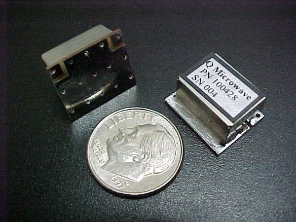
Figure 2. Miniature RF filter. Image used courtesy of Q Microwave
Performance Implications of Miniaturization
Reducing the physical size of a microwave filter changes its electrical behavior in several ways. Although the specific effects depend on the miniaturization technique, the following performance trade-offs are common in compact filter designs:
- Smaller resonators can concentrate current and electric fields in tighter regions. This can increase conductor and dielectric losses and lower the quality factor. A lower quality factor broadens the resonances and reduces selectivity, making the filter's frequency response less sharp.
- Small fabrication variations have a bigger effect on coupling strength in small structures. A slight change in conductor width, for instance, can produce larger deviations from the designed passband and distort the intended response.
- Compact structures can introduce parasitic resonances or higher-order modes that can create unwanted peaks or dips near the passband.
- Higher current density and stronger electric fields increase the risk of thermal effects, nonlinear behavior, and, at sufficiently high power levels, physical failure.
Design Techniques for Microwave Filter Miniaturization
You can address the challenges of microwave filter miniaturization by applying several design techniques:
- Use high-dielectric-constant materials.
- Apply capacitive or inductive loading.
- Optimize coupling structures.
- Integrate the filter into compact packages.
We’ll look at each of the four design methods in more detail in the subsections that follow. The best technique for your application will depend on your performance requirements and design constraints.
Use High-Dielectric-Constant Materials
Select a substrate with a higher relative permittivity (εr) to reduce your resonator's physical dimensions while maintaining the target frequency. Your guided wavelength decreases according to:
$$\lambda_g \approx \frac{\lambda_0}{\sqrt{\epsilon_{eff}}}$$
Equation 3
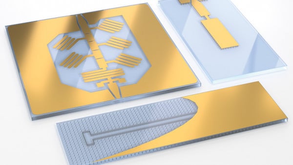
A higher effective dielectric constant generally means you need less physical length for a given electrical length (Figure 3). This allows your resonator to occupy a smaller footprint.
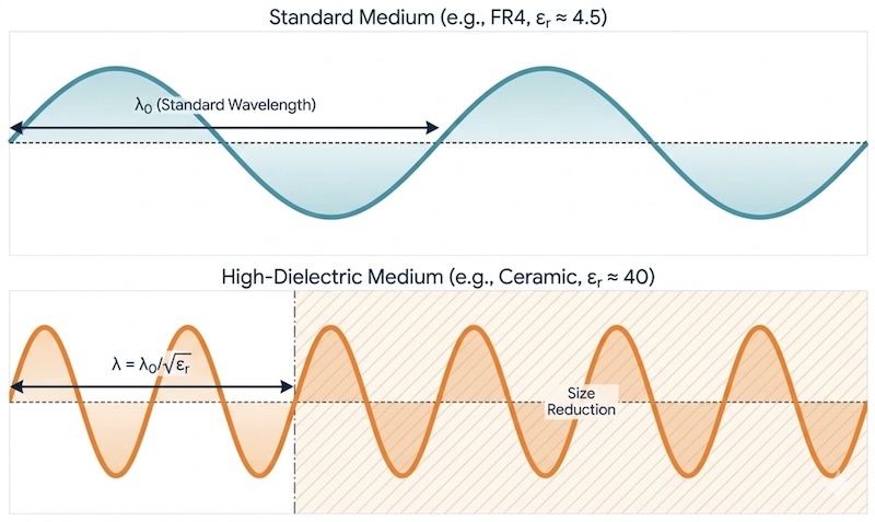
Figure 3. Increasing dielectric constant for wavelength compression. Image used courtesy of Q Microwave
When applying this approach, compare your materials based on their loss tangent (tan δ), thermal stability, and dielectric constant tolerance. A lower loss tangent can help you minimize dielectric losses, while good thermal stability can help you maintain your filter's performance consistently as temperature changes.
The dielectric constant tolerance is also important because variations in εr can shift your resonant frequency and affect coupling, especially in a compact design.
For narrowband or high-Q filters, you may need tighter fabrication tolerances because small dimensional variations can measurably shift your resonant frequency or coupling conditions, particularly as your guided wavelength decreases.
Apply Capacitive or Inductive Loading
You can also reduce the resonator's physical size by adding capacitance or inductance to the structure. Increasing either one lowers the resonant frequency. This allows you to use a shorter resonator while still achieving the desired frequency.
You can introduce capacitance through features such as interdigital capacitors or capacitive gaps. To increase inductance, you can use meandered or folded current paths that provide a longer electrical path within a smaller area.
When using loading elements, evaluate how they influence the resonator's Q factor, insertion loss, and unwanted resonances. These features can introduce additional losses and alter the resonator's electromagnetic behavior.
Optimize Coupling Structures
Adjust the spacing and coupling geometry between your resonators to achieve the required coupling coefficient for your target filter response. Since spacing, overlap, and orientation influence electromagnetic coupling, small layout changes can shift your bandwidth, insertion loss, and the locations of transmission zeros.
You can control coupling strength by modifying features such as coupling gaps, overlap length, resonator orientation, or aperture dimensions. For many coupled-resonator structures, reducing the gap increases electromagnetic coupling. If the coupling becomes too strong, you can increase the gap, reduce the overlap, or adjust the coupling region to bring the response back toward your desired bandwidth.
When you miniaturize your filter, optimize the coupling structure along with the resonator design. Shrinking the layout also changes the coupling between resonators, so you need to account for those changes to maintain your intended frequency response.
Integrate the Filter into Compact Packages
As you reduce your filter's size, also consider how the package and RF interfaces affect its electrical performance. Changes to the ground vias, connector launches, bond wires, and transmission line transitions are all important. They can alter the current paths and parasitic capacitance around the filter. This can shift the resonant frequency, change coupling, and affect impedance.
This becomes especially important when you place your filter closer to other RF components or change the surrounding ground structure. You may need to fine-tune the transition geometry, via placement, and resonator layout to maintain the desired coupling and impedance.
You can also use SMT packaging to reduce interconnect length and achieve a more compact assembly (Figure 4).

Figure 4. Surface mountable packaging for RF Filters. Image used courtesy of Q Microwave
However, you still need to account for the package parasitics and transition geometry when designing the filter. It's also important to ensure that your package does not introduce significant insertion loss, frequency shifts, or unwanted resonances.
Before finalizing the package design, evaluate the following factors to make sure the package and RF transitions do not introduce unintended changes to your filter's performance.
- Parasitic capacitance and inductance from pads, bond wires, vias, and package structures.
- Launch geometry from the transmission line into the packaged filter.
- Ground return path and via placement around the RF interface.
- Impedance matching through the package transition.
- Insertion loss and return loss introduced by the package and transitions.
- Resonant frequency shifts caused by package parasitics.
- Coupling changes between the resonators and nearby package structures.
- Higher-order or parasitic resonances introduced by the package.
- Transmission line discontinuities at the package-to-board interface.
Miniaturization Ultimately Comes with Trade-Offs
You can apply the above techniques individually or in combination to reduce the size of your filter while maintaining the desired operating frequency. However, no miniaturization technique preserves every aspect of filter performance.
That said, treat miniaturization as one design objective rather than the primary goal when designing microwave filters. In many aerospace and defense applications, achieving low insertion loss, a high quality factor (Q-factor), or high power handling is often more important than minimizing the filter's physical size.
Ultimately, the best design is not necessarily the smallest one, but the one that best satisfies the performance requirements of its intended application.
Feature image background used courtesy of Adobe Stock