Facebook
 Google
 GitHub
 Linkedin
How to Draw, Render, and Animate with Fusion 360
Learn how to use Fusion 360 to develop digital drawings, 3D renderings, and animations to help in the creations of complex designs.
As projects become increasingly complex, designers tasked with creating intricate products can no longer rely on antiquated methodologies. Simpler designs once required 2D drawings and nothing more. Today, designers must tackle a wide variety of things such as complicated geometries, a growing list of components, and mechanical and electronic complexities (and interdependencies).
Design documentation isn’t just more intricate than before. It’s pivotal in helping customers engage with — and understand — various products. Basic drawings cannot adequately convey constructions and features. It’s difficult (if not impossible) to pull apart a design with hundreds of components and make sense of it with a static drawing.
Digital drawings, 3D renderings, and animations help products come alive. In this article, learn how teams can make this happen using Fusion 360.
Making a Digital Drawing
Teams may decide to begin by crafting a digital drawing in the design phase. The drawing process is simpler than paper drawings requiring permanent edits or new drafts. Digital copies are easy to edit, streamlining and speeding up the overall design process. It’s also simple to save each subsequent version to keep tabs on progress.
Drawings are created within the Fusion 360 workspace. The drawing controls ribbon on Fusion 360 spans most of the window:

Figure 1. 2D drawings in Fusion 360.
Teams can customize their workspaces and drawings with the following toolbars:
- Drawing Views
- Modify
- Geometry
- Dimensions
The Drawing Views Toolbar
The Drawing Views toolbar allows easy visualization of layers, positioning tweaks, and layouts pertinent to a project. It also includes a Placeholder Views option with additional opportunities to use templates. The core views within the Drawing Views toolbar include:
- Parent View: gives a top-level view of one’s drawing.
- Projected View: allows users to create specialized views of selected parts within their drawings (top, side, front, etc.)
- Section View: allows users to select a portion of a part by pressing Enter, then visually manipulate it as desired. When part of the 2D drawing is selected, a 3D representation of that segment will appear until it’s dragged to the desired location (creating a new 2D drawing of that segment).
- Detailed View: allows users to zoom into a highlighted point and add dimensions, text, or other information.
The Modify Toolbar
The Modify toolbar functions are for more straightforward manipulations of a drawing or component — this includes rotating a component around a central axis. Users may also resize a design both vertically and horizontally. It’s also easy to move a component after selecting it. Autodesk lets users snap to different points within a drawing and unsnap by pressing Esc.
The Geometry Toolbar
These functions allow users to change the center lines within a design, draw new borders and parallel lines, expand shapes, create angles, and more. These actions are useful when working with both traditional and non-traditional geometric shapes.
The Dimensions Toolbar
By using the Dimensions toolbar, users can highlight an endpoint or center line, drag to another, and auto-generate a dimension based on positioning. A horizontal line is drawn between these two points. This line can rest directly on the drawing itself, or be drawn off to the side (to avoid obscuring the sketch). A measurement label is automatically created for future reference.
Selecting a border line (at the edge of a dimension) and dragging allows for the successive creation of new dimensions. This forms a contiguous chain of dimensional measurements between points, depending on how far one draws their lengths, saving alignment time. If the label is getting in the way, it can be dragged to a preferred location or snapped into place.
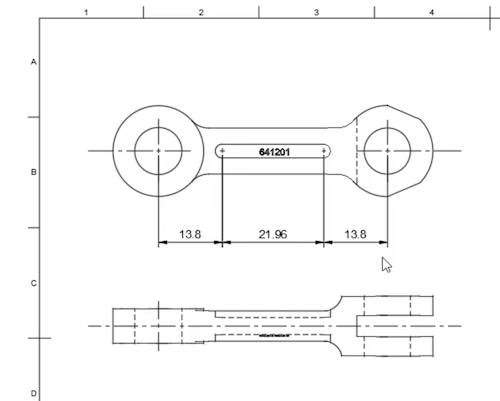
Figure 2. Drawing linear chains of dimensions is easy.
Teams can also add center-to-center dimensions, diameter dimensions, and more. The same goes for angled lines. Selecting a dimension and right-clicking brings up a menu of additional options. One can even repeat dimensions at other points of the design or measure angles as needed. Autodesk labels these angle measurements similarly to straight measurement labels.
Other Options
Teams looking to annotate can add text to any portion of the design. If symbols need to be added, the Symbol Toolbar can be used for a variety of units and calculations. Users can also insert their own images or add tables — the latter of which will autofill based on selections. Drawing is simple with Fusion 360, and it can be taken a step further by making 3D renderings and animations.
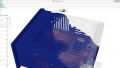
Making 3D Renderings and Animations
It’s often impossible to claim that documentation is complete without 3D assets. It can be hard to capture all intricate views of a product without observing it realistically from all angles, especially with complex designs. Manipulation and inspection become increasingly thorough when teams can rotate objects around a 3D plane.
Fusion 360’s 3D renderings give designers a clearer picture of how products will look in the real world. Designers can iteratively alter numerous characteristics as they go:
- Shape
- Color
- Materials and finish
- Focal settings and sharpness
- Depth of field
- Position
- Backgrounds
- Lighting and shadows
With in-canvas rendering, teams have access to real-time ray tracing and numerous options for rendering in varying quality:

Figure 3. Choose from a variety of options and formats within the Render Settings menu.
Teams create renderings to finalize their designs; however, they also do so to market. There are settings for web, mobile, print, video, and custom. Users can select from multiple platform-appropriate resolutions and file sizes change accordingly. Users can also alter the aspect ratio and exposure. These custom tweaks allow teams to create bespoke renderings that fit within fringe use cases (if needed).
Rendering Locations and Quality
It’s fully possible that a design is still in flux, hence the choice of a standard render quality — this version might not be top-quality. This saves precious space and computing resources.
The same principle applies to the Render With option in Fusion 360. Full-resolution, 3D renderings, and animations are often difficult to produce. A machine with powerful CPU-GPU capabilities may handle this without issues.
However, Autodesk is designed to run on any device with a web browser. Users without newer hardware may elect to render in the cloud as opposed to locally. This leverages Autodesk’s compute resources as opposed to one’s own. While renderings must be scheduled this way, the process can be completed in the background without sucking up system resources. Resource concerns grow larger when renderings are animated.
Animation Creation
Sometimes, a static drawing is not enough. Crafting an animation can be the best way to show users how a product works, how it comes together, and how key components interact. This is critical for marketing and conveying instructions for (dis)assembly.

Figure 4. Teams can fine-tune many aspects of an animation, including duration, positioning, transformations, and more.
While a static exploded view may be helpful, it might not be enough to fully realize a design. Fusion 360 takes things further by offering an animated explosion view, which can be created automatically with most designs. By making this process into a video, stakeholders can see how products come together — and apart — in a loop.
Manual and Custom Controls
Fusion 360 allows designers to tweak every parameter possible within an animation, ensuring users can create the right view without excluding crucial details. Rotations, translations, obfuscation, and viewing angle alterations are possible to numerous degrees. On a deeper level, this includes:
- Selected components
- Pivot points
- X, Y, Z distances
- X, Y, Z angles
- Trail line visibility
- Split transformations
Keys are automatically generated to match these inputs. As an example, let’s say a team is making assembly instructions. Once these instructions are completed, they may simply be copied in reverse for disassembly. There is no need to create another process from scratch. A storyboard depicts the animation in an easy-to-view layout. Additionally, all components are listed to the left of the workspace. This list may be expanded or collapsed for quick consumption.
Those wanting to include annotations for context may do so. Once the animation is finalized, it’s easy to preview that animation right from the control strip within the View Toolbar. A drop-down menu provides viewing options. Once teams are ready to publish, they can save the animation file in MP4 format and choose from a list of resolutions and aspect ratios, just like one would do with a rendering.
Any updates to designs and animations are saved automatically to the cloud. These updates are reflected across all devices and platforms.
Modern Products Deserve Modern Documentation
Today’s complex products help professionals (and customers) tackle numerous challenges. However, that means documentation practices for designers must evolve, modernizing the design process in tow. Drawings, renderings, and animations are now indispensable tools that teams must leverage to effectively capture design nuances.
This article outlined a traditional workflow, in which drawings are step one in the process. Note that Fusion 360 users with a rendering may also create drawings from those objects. This flexibility doesn’t restrict users to one process. Whichever assets are available may serve as blueprints for future development.
Stakeholders are also more diverse today, allowing designers to share documentation from anywhere in a format that works for everyone. Whether teams are designing PCBs or mechanical parts, tools like Fusion 360 can help streamline development.
Related Content