 Facebook
 Google
 GitHub
 Linkedin
Designing Microelectronics Using Fusion 360
This article dives into how Fusion 360 can be used to produce smarter microelectronics.
The microelectronics world has marched forward drastically since the 1936 invention of the PCB. Electronic components had shrunk precipitously — conversely growing more powerful — to the point where designing them had become increasingly challenging. Tape and mylar diagrams were insufficiently intricate and took ages to assemble if such a layout was even feasible. The industry needed a modern solution.
Modernization Through Combination
The ensuing decades ushered in fundamental changes to electronics design. Individual trailblazers and companies alike published successive versions of design software. Included in that innovation was EAGLE for PCB/schematic design in 1988, followed by Fusion 360 twenty-five years later.
These two applications have since joined forces. This article dives into how Fusion 360 can be used to produce smarter microelectronics.
Leverage MCAD and ECAD Together
Engineers are often put in charge of developing complete electronic products such as small robots or handheld devices. The design requires numerous, sensitive components crammed together into minute spaces. Consumers accordingly expect these miniaturized devices to do more than ever before. CPUs and GPUs containing millions-to-billions of transistors deliver plenty of computing power, yet generate high heat at peak load.
Wattage and power draw contribute to thermal performance in compact spaces. Companies often rely on passive cooling — internally through heatsinks, externally via casing materials like metal and plastic — or copper heat piping, as seen in previous Qualcomm Snapdragon processors. Power management ICs must help prevent devices from simultaneously overheating and running out of juice.
Devices must be self-preserving (protecting internals like wires, glues, and silicon from premature degradation) while preventing user injury. Are poor thermals also causing performance throttling? These are all key elements to consider while creating electronics.

Figure 1. A cross-section of a casing and its integrated circuit boards.
Fusion 360 accounts for these concerns. Often, designers work with both silicon components and enclosures in lockstep; these designs may be performance-driven (adapting the enclosure accordingly) or form-factor driven (adapting core components to fit within). Combining MCAD and ECAD provides a unified design interface, allowing engineers to refine all design aspects within a single application. This is done in different ways:
- By presenting users with an interface that combines projects in one window, eliminating the need to bounce between programs
- By offering external enclosure views, cross-sections, macro board layouts, and detailed PCB schematics (showing connectors, wire bends, labels, layers, etc.)
- By granting access to online catalogs and libraries (see tip #7) of resources, spanning MCAD/ECAD/CAM
- By giving users unified toolbar categories for DESIGN, DOCUMENT, VALIDATE, and AUTOMATE

Figure 2. A tabbed interface meets rich iconography and workspaces.
From Iterative Design Completion to Thermal Evaluation
With a design completed ‘on paper,’ validating thermals via Fusion 360 comes next. Interactive simulations accurately display temperature readouts and designers can adjust a sliding temperature scale to view critical information:
- Hot spots and their relationships with nearby components
- The total number of components and the impacts of full-scale operation on overall thermals
- Maximum device operating temperature
- A list of all components in descending order, according to their operating temperatures

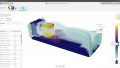
Figure 3. A diagram depicts how temperatures fluctuate across different areas in a device.
The figure above shows how heat spreads throughout an enclosure during usage. Fusion 360 can show where heat dissipates — here, at the enclosure frame nearest the external environment — and where it congregates. These lists and visualizations accomplish a few things. They can tell engineers where thermal optimizations are needed and can reveal whether or not individual internals are performing to spec.
Teams can also cross-reference temperatures with materials constraints. For example thermoplastic ABS — a common housing for handsets and appliances — has a service limit of about 70°C (158°F). ABS loses roughly 25% of its mechanical strength due to softening at this threshold. The Fusion 360 simulation can show if any components acutely exceed this temperature at peak or for an extended period during operation. If any components do exceed this temperature, one of three things must happen:
- Improved housing materials must be introduced
- Alternative components must be integrated which perform better within that form factor
- A new enclosure design (or internal layout) is needed, to promote better thermal dissipation or localization
Fusion 360 helps engineers make informed decisions around product improvement. Iterations can boost performance and long-term reliability. These data-driven refinements reduce guesswork and costs.
Mechanical Notes and Compatibility
Design integration becomes increasingly important with robotics (for example), where electronic and mechanical components must coexist. The robot’s composition — form factor, wiring, power-and-drive components — must be balanced. Its core functions (especially motion) mustn’t be hampered by haphazard electrical engineering, and vice versa. These systems must complement one another.
Moving parts are generally subjected to stressors: repeated movements, directional force, and friction impact durability. Fusion 360’s mapping software paints a clear, holistic picture of mechanical performance.
How Electronics Design Helps Manufacturing Sustainability
Fusion 360’s schematic editor provides access to thousands of components. Experimenting with different materials and arrangements is simple. The library is designed to work seamlessly between multiple sheets. Relatively speaking, creating complex, layered circuit boards becomes a simpler task.
Fusion 360 allows designers to edit attributes and design parameters without obstructing your workspace. This is accomplished by using the Design Manager panes in the window’s right side:

Figure 4. The editor sidebar provides drop-downs and manual inputs for granular tuning.
The SPICE simulation tool offers a way to explore the feasibility of final designs. The truth remains that a product must be optimized and performant under realistic conditions regardless of how beautiful its outward appearance. This closing stage of the design process validates performance prior to launch. If things check out, manufacturing soon follows.

Figure 5. Clearly-labeled graphs show component performance across a range of conditions.
A final facet of Fusion 360 is designed for manufacturability (DRC). Built-in rule checkers compare existing design elements to sets of constraints. While it’s tempting to go all-out on a product, costs at scale might prevent it. This is one reason silicon diodes won out over their germanium counterparts, for example. DRC helps engineers pair materials with fabrication methods, ensuring companies can fulfill demand. This rule checker also checks multiple PCB layers in tandem — another time gain.
Fusion 360 has helped to change how teams create their microelectronics. The centralized application can help cut costs, shorten the design process, and interconnect stakeholders across all departments.
Related Content


o ªªª no Fusion 360
https://hackaday.com/2020/09/16/autodesk-announces-major-changes-to-fusion-360-personal-use-license-terms/
DRC = Design Rule Check(er)
DFM = Design For Manufacturability
They overlap to some extent, but they are not synonymous.