Facebook
 Google
 GitHub
 Linkedin
How to Verify and Validate Designs Using Fusion 360
This article discusses why verification and validation matter in design, how they differ, and how applications help teams incorporate and enrich their workflows.
During the creation process — especially as production becomes increasingly complex — it’s important to know the ins and outs of the design to ensure a successful end product. Moving parts, intricate electronics, and space-age materials distinguish each from the next, and combining these elements together into one cohesive, functional package is essential. In this article, learn about how this can be accomplished through design verification and validation using Autodesk’s Fusion 360 design software.
Design verification and validation are two core processes that guide development from inception to manufacturing, ensuring that product designs are adequately refined. Verification and validation provide agnostic templates for upholding best practices and, ultimately, enhancing user outcomes.
Despite their ubiquity, however, many professionals falsely use these terms interchangeably. This article will assess why verification and validation matter, how they differ, and how applications help teams incorporate and enrich their workflows.
What is Design Verification?
Design verification is a comprehensive tool that plays an essential role in everything from planning to performance assessment. Typically, verification is initiated first, though it can take hold at multiple developmental stages. This process confirms that design requirements have been objectively fulfilled. Inputs are essential and having a working template can result in cost and time savings. Without verification, designs can also become materials intensive, straining supply chains, and impacting external suppliers with limited inventory.
The following steps are involved in design verification:
- Comparisons between background data and proposed features
- Specification reviews and input evaluation
- Measurement confirmation, product analysis, and generative inspection
- Developing test plans according to existing or prospective samples
What is Design Validation?
Validation contrasts with verification in that it occurs at two primary stages: after confirming user needs, and following final production. Validation can occur in the following ways:
- Simulating real-world usage by users
- Gathering external user feedback (after a market launch)
- First-hand usability testing with finalized prototypes
Validation can include market research as well. It is likely that designers will compare devices and products to competing options which is an important step to take in ensuring that a product doesn’t copy another, underperform, or drown in a saturated market.
Validation also involves usability testing — prioritizing interactivity and user clarity over physical testing (e.g. strength testing). The process focuses on user experience (UX), thus taking into account environments, operating conditions, and varying user aptitude.
The steps involved in verification and validation might seem overwhelming at face value. However, many of these tasks can be offloaded onto a preferred CAD and CAM application. Automation, improved organization, and collaboration all aid in getting quality products out the door.
Getting Started with Verification
As is necessary for later validation, begin with opening a CAD/CAM program, which is the conduit through which designs come alive. The precursor to design is its inputs — the unique parameters that give products their form factor, functionality, and scalability.
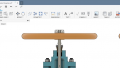
For example, imagine that a company is designing a latch link. This part is one component in a system, and its design must be functional and ergonomically sound. This ensures comfortable operation with an integrated form factor. The overlay pane is where you might determine basic finishing, like edging and shaping:

Image courtesy of Autodesk.
This example is relatively simple, as the goal is to design a component with four basic parameters. How many edges are needed, whether those edges are symmetrical, and the width of the chamfering should all be taken into consideration — comparing predetermined metrics with workspace inputs is essential to finding answers. This is where adjustments may be necessary — to ensure interlocking parts operate effectively and maintain a consistent design language. Utilizing translucent schematics and geometric comparisons make this an easier task.
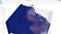
Many of today’s components are complementary, often residing alongside other components within a compact enclosure. There are many things to consider when designing an air quality sensor:
- Enclosure dimensions
- PCB dimensions, including thickness
- Dimensions of accompanying components (SoCs, batteries, supplemental chipsets)

Image courtesy of Autodesk.
To verify design viability, teams can complete the following tasks:
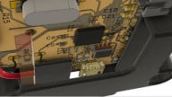
- Add the base PCB into the editor
- Draw and arrange any critical circuitry, including elements (resistors, capacitors, diodes, transistors, etc.), signals, and primitives (tracks, pads, vias, fills, arcs, and strings)
- Confirm that the total number of these is correct (inspection process)
- Cross-reference component dimensions and packaging with restrictions imposed by the enclosure (in this case, perhaps a smart thermostat or carbon monoxide detector body). Will it fit on its own and alongside other components?
- Augment the design or rework the enclosure if compatibility issues arise
It’s possible to move the goalposts during verification since the design process is iterative. However, marketing and design teams can often battle over priorities. If one team won’t budge on a particular aesthetic, every design stage grows more challenging. Creating alternative configurations can sidestep this problem prior to testing, especially if CAM checklists identify production bottlenecks.
How to Test
Crafting a viable design is one thing, but teams must also confirm performance under real-world conditions, and doing so might not be optimal with a finalized product. Teams can thus accomplish this by running simulations within Fusion 360. Below are two examples (stress testing and thermal testing):
Stress Testing

Testing how a metal support beam flexes in response to load. Image courtesy of Autodesk.
Not all designs are electrical or mechanical. Solid-state designs (like support beams and construction materials) encounter diverse stressors throughout their lifespan, meaning they must be resilient. Here’s how load simulation can determine a product’s strength:
- Have the simulation apply a directional force to the object, either acutely focused or evenly spread across its entire length.
- Make the force dynamic by changing directions, spread, and magnitude.
- Measure displacement (or deflection) at different points across the product.
- Alongside mapping, assess whether these measurements comply with safety-and-integrity standards (i.e., ensuring it will hold up over time).
Thermal Testing (CFD)

Thermal mapping shows how temperatures fluctuate at key points within a design. Image courtesy of Autodesk.
Electronics and moving parts generate plenty of heat due to electrical current generation and friction. Keeping these temperatures within limits is crucial to safety, longevity, and product integrity. The following steps show how an electronics thermal simulation might come together:
- Verify that inputs emulate real-world operation (dynamic load and power draw, plus usage duration).
- Run the simulation with all components active, both under stress and at relative rest (low-power state).
- Inspect the thermal mapping to view thermal spikes, heat sinks, and dissipation (alongside with the range graphic). It’s important to note the minimum and maximum temperatures.
- Thermal simulation generates a list of all components arranged by their operating temperatures. Compare these with the project constraints, and identify where reconfiguration might be needed to optimize thermal performance.
Validation Procedures
Once teams have a working product, the first production batch can soon become a reality. This is a critical point in manufacturing because it marks the point where public testing begins and allows assessment of product performance in a realistic fashion.
Reducing unknowns is the primary goal for many designers, which is why processes like verification and validation are so important. Validation allows designers to see how simulated use stacks up against actual use. Although numerous parameters can be fine-tuned within simulations, products (especially portable electronics and automobiles) face unpredictable operating conditions as they will in the real world.
Sharing Data with Stakeholders
Data-gathering is the final key step to product refinement. It’s also why initial product batches may be notoriously flawed compared to their successors. Companies make adjustments and solve problems reactively (for example, an automaker making engine refinements in response to feedback). The observation process itself is relatively passive. Conversely, product improvement is an ongoing process requiring designers and engineers to accurately interpret statistics.
All products matter to varied stakeholders: designers, marketers, investors, engineers, and others. As mentioned previously in this article, product comparisons are essential, and this is where that comes into practice. Many products exist within competitive segments, which is why designers should know how their reliability compares against that of others. Fostering an open, collaborative pipeline is key to swift product improvement.
Administrative tools determine which stakeholders have access to crucial information as it becomes available. Sharing and exporting files in industry-standard formats (STEP, DWG, DXF, OBJ, STL, IGES) is useful for keeping authorized users on the same page, cutting validation time while reaffirming any commitments to users.
Digital Design is Intelligent Design
Product creation is undoubtedly complex, and verification and validation can be invaluable processes for many product teams, paving the way for widespread customer satisfaction. Until present times, companies have not had such powerful software suites at their disposal, and these applications are helpful for many designers. Tools like Fusion 360 can automate the daily challenges teams face, allowing for sound designs from the beginning.