Facebook
 Google
 GitHub
 Linkedin
Improving Low Dropout Voltage Regulation Using Remote Sense
Learn how remote sensing for low dropout (LDO) regulators can counteract parasitic resistance and inductance in applications with long connections, narrow traces, or high power.
In circuit design, managing parasitic effects in power supplies is crucial, particularly in high-current applications where long connections or narrow traces can compromise performance. Remote sensing minimizes voltage drop and provides precise voltage regulation.
This article examines remote sensing for low dropout (LDO) regulators to counteract parasitics between the LDO output pin and the load. We will compare operations with and without remote sensing using the Renesas SLG51003 power management IC (PMIC) for two typical use cases.
What Is Remote Sensing in LDO Regulators?
Maintaining precise voltage delivery at the load can be challenging due to significant voltage drops in high-current applications and systems utilizing long or high-resistance power supply lines. Remote sensing offers an effective solution by monitoring the voltage directly at the load instead of at the LDO output.
This innovative approach compensates for voltage drops caused by parasitic resistance and inductance, ensuring the load receives the intended voltage. This capability is particularly critical in systems employing flexible cables, where parasitic effects are more pronounced.
Configuring the LDO Regulator in Remote Sense Mode
On the SLG51003, Remote Sense mode can be utilized by LDO1 (LDO_HP) to regulate the voltage on the load side. In this mode, the GPIO1 pin is configured as an analog input to serve as the Remote Sense pin. GPIO1 should be connected to the load that is powered by LDO1.
Using Remote Sense mode on LDO1 can be especially useful in the following conditions:
- Systems with long wires or flexible printed circuit connectors. In applications where the load is physically far from the LDO, the wiring or traces can cause a voltage drop.
- Systems with precision analog circuits. For sensitive applications like data acquisition, even small variations in supply voltage can affect performance.
- High-current applications. Significant voltage drops can occur within the distribution lines in circuits where large currents are drawn.
Remote Sense compensates for the voltage drops by adjusting the output voltage to maintain the required voltage level at the load. Load regulation performance depends on the parasitic parameters of the system. Therefore, the electrical specifications for LDO1 can be affected in Remote Sense mode operation.
Because the GPIO1 pin relies on VDDIO, the VDDIO voltage should be higher than the voltage at the LDO1 output.
Comparing LDO Performance With and Without Remote Sense
Figures 1 and 2 show two circuits: one without Remote Sense and one with Remote Sense. The circuit with Remote Sense compensates for the voltage drop caused by parasitic parameters (inductance and resistance) on VOUT1.
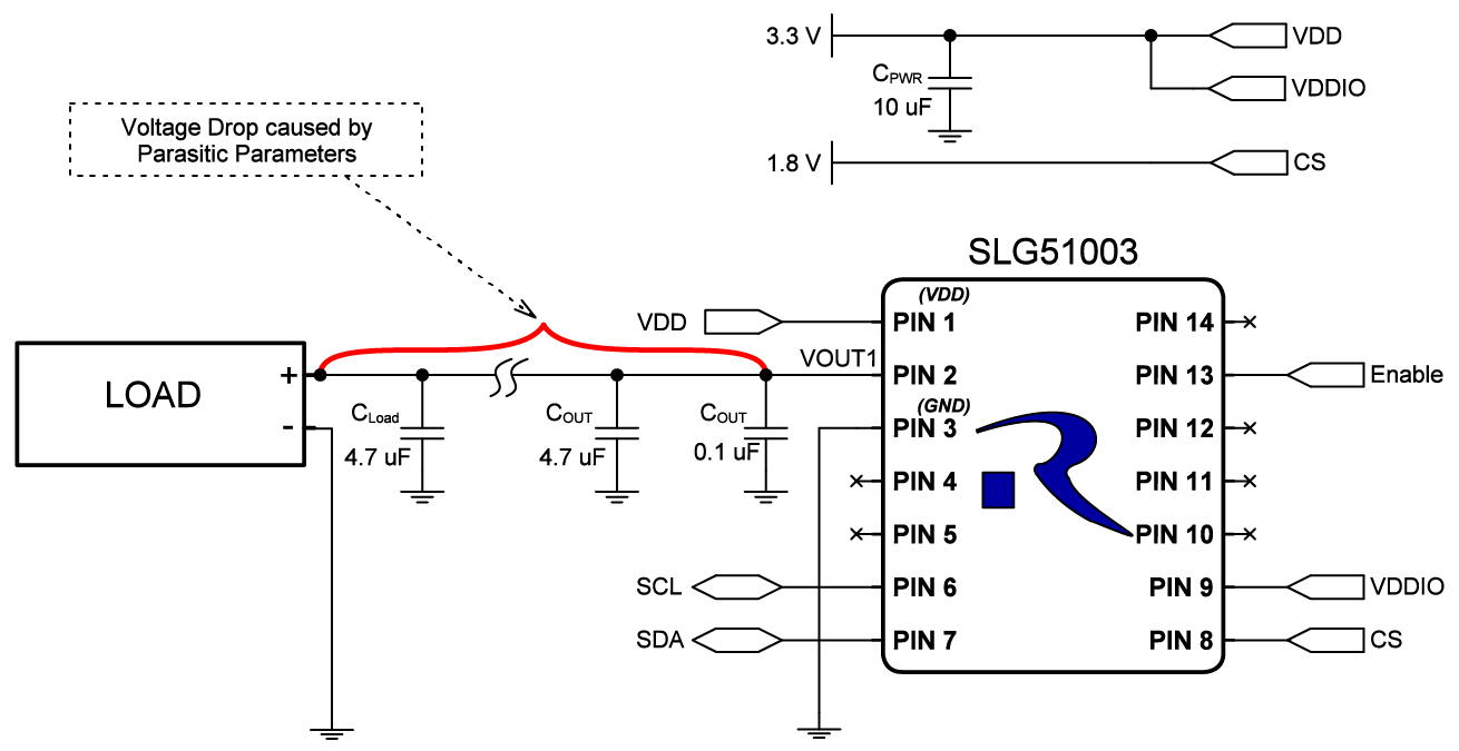
Figure 1. Typical LDO voltage regulator application circuit without Remote Sense. [click to enlarge]
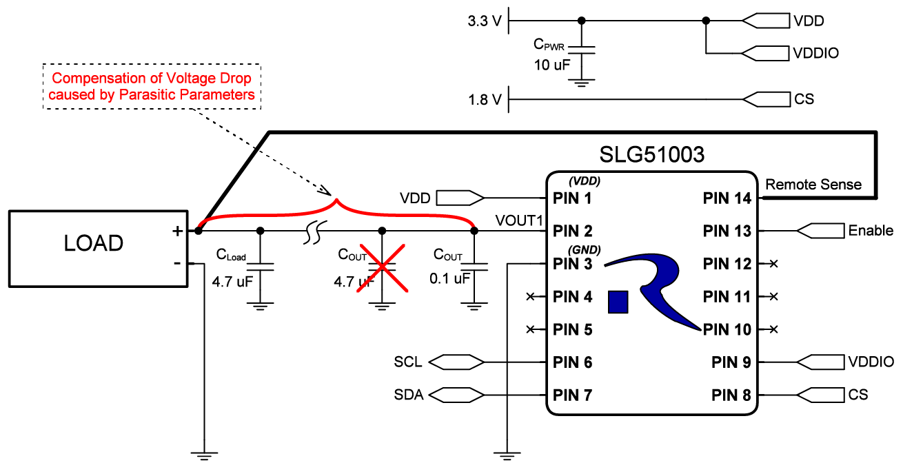
Figure 2. LDO voltage regulation circuit using Remote Sense mode. [click to enlarge]
Using Remote Sense also allows us to remove the large 4.7 µF capacitor near the IC, leaving only the small 0.1 µF capacitor in a 0201 package. This will help to reduce the solution cost and decrease the overall PCB area.
Remote Sense Mode for Long FFC Connections
One application where LDO Remote Sense can be beneficial is when flexible flat cables (FFC) are used. Flex wires are used where compact, flexible, and reliable connections are needed. They are often found in mobile devices, connecting displays, touchscreens, and cameras to save space and reduce weight.
In Figure 3, two boards are connected by flexible flat cables (FFC). The left board has an SLG51003 with Remote Sense mode capability. The load and a 4.7 µF capacitor are located on the board on the right. The GPIO1 signal is also connected near the load on the right to monitor the load voltage.
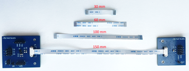
Figure 3. Test setup for comparing LDO regulation across FFCs of different lengths.
The input voltage of the SLG51003 is 3.3 V, and the output voltage is set to 2.85 V. The load is adjustable up to 475 mA. In the default LDO operating mode without Remote Sense, the output voltage drop can be observed by gradually increasing the load current.
In Remote Sense mode, the voltage drop is compensated for at the VOUT pin.
DC Load Regulation Using Remote Sense
Table 1 compares the output voltage with and without the Remote Sense mode for 10 and 475 mA loads for four different FFC wire lengths.
Table 1. Comparison of the voltage drop with and without Remote Sense for two load currents and four FFC wire lengths.
| Wire Length (mm) | 30 | 60 | 100 | 150 |
| Trace Resistance (mΩ) | 67.6 | 98.8 | 144.8 | 202.7 |
| Without Remote Sense | ||||
| VOUT @ 10 mA | 2.85 V | 2.85 V | 2.849 V | 2.848 V |
| VOUT @ 475 mA | 2.816 V | 2.802 V | 2.781 V | 2.753 V |
| Voltage Drop | 33.5 mV | 47.3 mV | 68 mV | 97.4 mV |
| With Remote Sense | ||||
| VOUT @ 10 mA | 2.853 V | 2.853 V | 2.853 V | 2.853 V |
| VOUT @ 475 mA | 2.847 V | 2.844 V | 2.839 V | 2.833 V |
| Voltage Drop | 6.2 mV | 9 mV | 13.9 mV | 19.6 mV |
Figure 4 plots the voltage difference (∆VOUT) on the load side with Remote Sense (solid lines) and without (dashed lines).
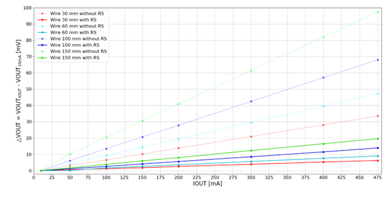
Figure 4. Voltage drop comparison on LDO1 with/without Remote Sense for different wire lengths.
The voltage difference calculation uses the voltage measured with a 10 mA load as the baseline. The figure clearly shows how Remote Sense compensates for voltage drop along the trace.
Note: The SLG51003 can only compensate for the voltage drop on the LDO1 output trace. The parasitic parameters at GND can still affect the circuit and cause some voltage drop at the LDO1 output. Therefore, proper GND routing on the PCB is extremely important in these types of applications.
Transient Effects of Remote Sense LDO Regulation
To evaluate the transient response during Remote Sense mode, a controlled, fast-switching load is applied to the LDO. This simulates real-world scenarios where the connected load might fluctuate rapidly. The test assesses how quickly and accurately the LDO can stabilize its output voltage when the load current rapidly increases or decreases.
The results of the load transient tests are shown in Figures 5 and 6, with and without Remote Sense.
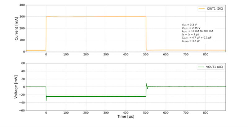
Figure 5. LDO1 load transient without Remote Sense.
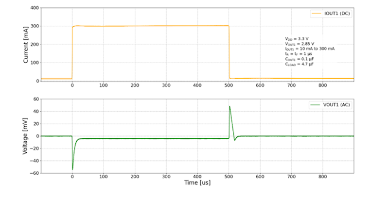
Figure 6. LDO1 load transient with Remote Sense.
Based on the figures above, it can be observed that when the Remote Sense mode is enabled, voltage spikes are larger than without the Remote Sense mode, but the voltage drop is much lower once the current is stabilized.
Startup Currents and Remote Sense
Figure 7 shows the results of a startup current limit test. The startup current limit for LDO1 is configured to 240 mA. A resistive load current of ~270 mA is applied to VOUT1, and LDO1 is enabled.
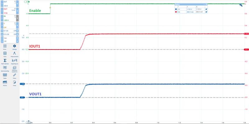
Figure 7. LDO1 startup current protection with Remote Sense mode.
As the transient response demonstrates, the LDO with Remote Sense responds properly with a load current that exceeds the configured startup limit.
Functional Current Limits and Remote Sense
In Figure 8, the results of a functional current limit test are shown. LDO1 is enabled, and then a load current of ~690 mA is applied to VOUT1.
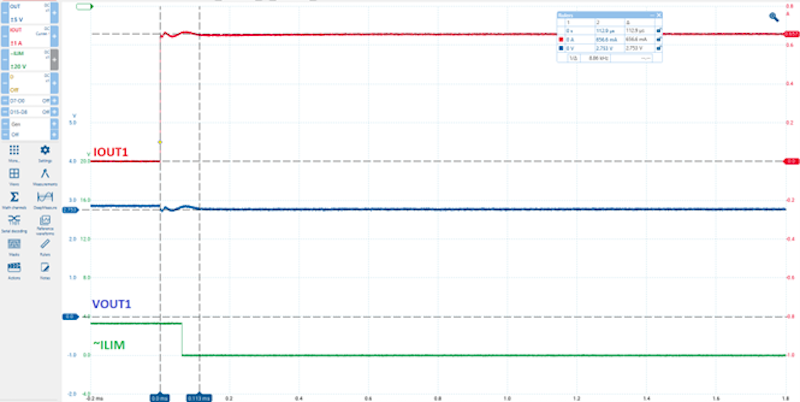
Figure 8. Operating waveform of LDO1 functional current protection with Remote Sense mode.
Although the load current exceeds the chip’s current limit, the LDO with Remote Sense provides functional current protection.
Remote Sense Mode for PCBs with Long Traces
Another use case for using Remote Sense mode is when the load is located far from the IC on the PCB. At higher currents, the voltage drop becomes more noticeable depending on the VOUT trace length, width, and copper area used.
A test board with different trace lengths is shown in Figure 9. The SLG51003 is configured with the same settings as in the previous test setup with the FFCs.
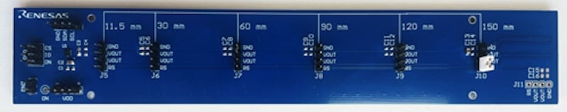
Figure 9. Test setup for comparing LDO regulation across PCB traces of varying lengths.
Table 2 shows that as the trace length increases, the voltage drop across the load without Remote Sense also increases.
Table 2. Comparison of the voltage drop with/without Remote Sense for two load currents and various PCB trace lengths.
| Trace Length (mm) | 30 | 60 | 150 |
| Trace Resistance (mΩ) | 27.7 | 33.1 | 48.3 |
| Without Remote Sense | |||
| VOUT @ 10 mA | 2.851 V | 2.851 V | 2.851 V |
| VOUT @ 475 mA | 2.838 V | 2.835 V | 2.828 V |
| Voltage Drop | 13.3 mV | 15.8 mV | 23.2 mV |
| With Remote Sense | |||
| VOUT @ 10 mA | 2.851 V | 2.851 V | 2.851 V |
| VOUT @ 475 mA | 2.845 V | 2.845 V | 2.845 V |
| Voltage Drop | 6.3 mV | 6.3 mV | 6.3 mV |
Without Remote Sense, the voltage sags by tens of millivolts at the maximum current of 475 mA. However, the difference can be compensated for thanks to the Remote Sense mode function. The output voltage drop when using Remote Sense mode is the same for each given distance and significantly smaller than without this function.
Figure 10 plots the load voltage difference (∆VOUT) for different PCB trace lengths. The voltage difference is calculated between the voltage at 10 mA load and other load current points.
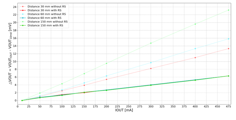
Figure 10. LDO1 comparison of the voltage drop with/without Remote Sense for different PCB trace lengths.
This figure clearly indicates that the Remote Sense mode successfully compensates for the voltage drop on the trace.
Configuring the SLG5100 Eval Board for Remote Sense
If you would like to get started testing Remote Sense, download and install the Go Configure Software Hub. Then, download this example design file and open it with the Go Configure Software Hub. Your screen should appear as shown in Figure 11.
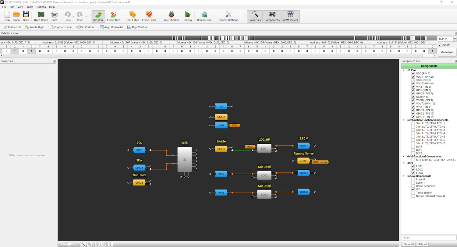
Figure 11. Go Configure Software Hub after loading the example Remote Sense design file. [click to enlarge]
You can also complete the following steps to enable the Remote Sense function for LDO1 with the SLG51003 Evaluation Board:
1. Connect the EVB (with the SLG51003) by USB cable to the PC.
2. Open the Go Configure Software Hub and choose the SLG51003.
3. Open the LDO1 settings and enable the Remote Sense function, as shown in Figure 12.
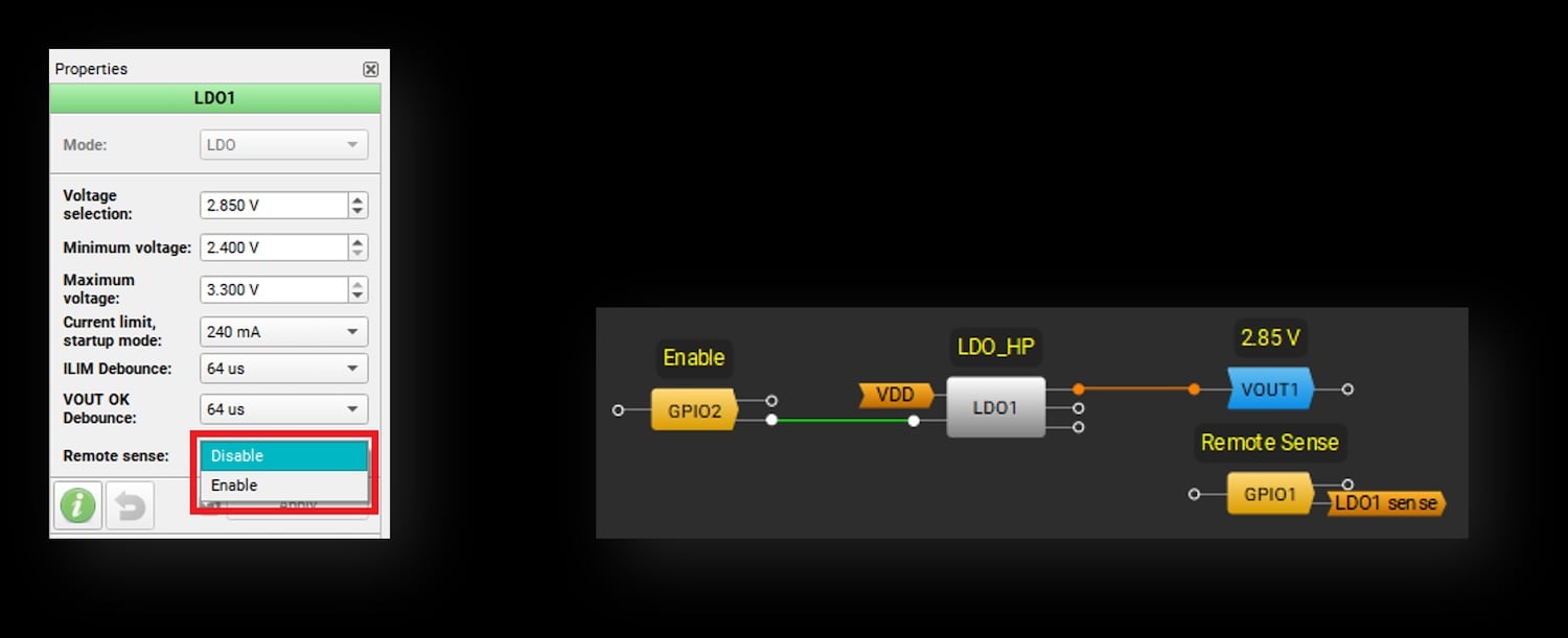
Figure 12. LDO1 settings in the Go Configure Software Hub to enable Remote Sense. [click to enlarge]
4. Configure GPIO1 as an Analog Input. The VDDIO power supply voltage in Remote Sense mode should be higher than VOUT1 but not higher than the VDD voltage.
5. Connect GPIO1 to the load or any other point on the PCB where the VOUT1 voltage level needs to meet the application requirements and enable LDO1.
After configuration, the voltage near the load will be maintained with high accuracy, and any voltage drop detected between the IC and the load will be compensated for.
Conclusion
The SLG51003’s Remote Sense mode enhances the performance of its high-precision LDO1, offering improved voltage accuracy across the load. This feature, configurable through the LDO settings, provides a valuable tool for optimizing load regulation in systems where parasitics can impact performance. Additionally, the SLG51003’s comprehensive Power GreenPAK features—including I2C support, GPIOs, configurability, status indicators, and sequencing—ensure flexibility for diverse project applications.
All images used courtesy of Renesas Electronics.