 Facebook
 Google
 GitHub
 Linkedin
A New High-Performance Digital MEMS Microphone from Infineon
Here's a breakdown of Infineon's new high-performance digital MEMS microphone that offers power-optimized modes for low-current consumption devices.
Here's a breakdown of Infineon's new high-performance digital MEMS microphone that offers power-optimized modes for low-current consumption devices.
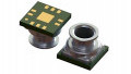
Infineon, a semiconductor manufacturer known for their microcontrollers, communication ICs, and power electronics, recently announced the IM69D120, which is a high-performance digital MEMS microphone. This MEMS-plus-ASIC (application-specific integrated circuit) 5-pin device comes in a unique package that measures only 4 × 3 × 1.2 mm.

Figure 1. The IM69D120 is a 5-pin MEMS microphone that comes in a specialized, yet small, package. Images taken from datasheet (PDF).
This MEMS microphone is based on Infineon's Dual Backplate MEMS technology. It offers high linearity (<1% total harmonic distortion up to 118 dBSPL) and a flat magnitude response from about 100 Hz to 10 kHz.

Figure 2. The IM69D120's free field frequency response, taken from the datasheet (PDF).
Optimizing for Low Power
Reduced power consumption is accomplished by lowering the IC's fclock; as is generally the case with integrated circuits, lower operating frequency corresponds to lower current consumption. The trade-off is that the SNR (signal-to-noise ratio) gets worse as fclock slows down. This is not surprising, however, because the clock determines the audio sampling rate, and we expect SNR to decrease as sampling rate decreases.The plot below shows how fclock affects current consumption and SNR.

Figure 3. As fclock slows down, current consumption decreases but SNR gets worse. Plot taken from the datasheet (PDF).
And speaking of changing fclock, you might be wondering how this is accomplished. The general idea here is that the IM69D120 is controlled by another IC, such as a microcontroller or DSP. The processor provides the clock, and the IM69D120 provides the digitized audio data. Thus, varying the clock frequency according to noise and/or current-consumption requirements is as simple as changing the frequency of the clock signal generated by the processor. The following diagram shows a typical implementation, where “CODEC” represents whatever IC is controlling the microphones and processing their data.

Figure 4. An example of a stereo-mode implementation, from the datasheet (PDF).
THD Levels
As mentioned previously, the THD (total harmonic distortion) of this IC is no greater than 1%, as long as the SPL (sound pressure level) is no more than 118 dB. It should be noted that this IC has an AOP (acoustic overload point) rating of 120 dB (typical); as shown in the next plot, the THD increases rapidly starting at about 117 dB, reaching a whopping 10% at 120 dB.
Keep in mind that 120 dB is quite loud (think rock concerts and jet planes), and that sort of volume can cause severe irritation to the ear, according to this noise thermometer (PDF). In other words, the major increase in THD that occurs at ~120 dB is probably not a serious concern in most applications.

Figure 5. THD (total harmonic distortion) vs. SPL (sound pressure level); a lower THD is better. Plot taken from the datasheet (PDF).
Footprint and Stencil Recommendations
Infineon has provided footprint and stencil suggestions, which is a good thing, because the package is by no means standard and because this IC requires an adequately sized hole in the PCB (see the recommendations in the figure below).
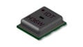
If you’re wondering why the PCB needs a hole (for sound entry), take another look at the photograph shown near the beginning of this article. The IC’s acoustic entry port is on the bottom of the package. This might seem like a rather counterintuitive arrangement, but it can be easier to create an optimized acoustic design when the microphone is mounted on the bottom of the PCB (take a look at this app note for more information).

Figure 6. Footprint and stencil recommendations for the IM69D120, from the datasheet (PDF).
An Evaluation Kit
The IM69D120 evaluation kit, according to Infineon, allows for "simple and easy evaluation" of this MEMS microphone. This assumes, of course, that you already have your audio testing setup ready to go. The eval kit comes with one adapter board and five IM69D120 ICs, each mounted on its own flex board (see image below).

Figure 7. The IM69D120's evaluation kit includes one adapter board and five eval boards. Image courtesy of Infineon.
Have you had a chance to use this new MEMS microphone from Infineon, or its evaluation kit? If so, leave a comment and tell us about your experiences.


Getting the I2S controller on an MCU to work with a i2s MEMS device is the worst.The MCUs I have worked with have very poorely designed SW libraries to support devices on their I2S buses.