Facebook
 Google
 GitHub
 Linkedin
Deep Dive Into Test Equipment Design: A Look at Tektronix’s 5-Year Process
All About Circuits met with the Tektronix engineers behind the 7 Series to uncover the myriad of design challenges that most people never hear about.
Oscilloscopes are the source of truth for electronics. Every new interface standard, every research experiment, and every aerospace communication link must eventually pass through their probes. When engineers see a measurement on a scope, they trust it implicitly.
But what rarely comes to mind is just how much engineering effort goes into making the instrument itself. Behind every screen full of waveforms is a decade of design trade-offs, cross-disciplinary collaboration, and even mundane practicalities like shipping logistics and fan acoustics.
All About Circuits had the chance to visit Tektronix headquarters in Beaverton, Oregon, to hear from the engineers behind the 7 Series and uncover the myriad of design challenges that most people never hear about. You can read our coverage of the 7 Series announcement earlier this week here: Tektronix Launches First Flagship Performance Oscilloscope in Over 10 Years
A Convergence of Disciplines
Designing an instrument like the 7 Series DPO isn’t a job for a single team. It requires hundreds of engineers closely collaborating across a variety of fields. A single oscilloscope of this complexity calls on expertise in PCB design, ASIC design, system integration, firmware, software, mechanical engineering, and compliance, to name a few. Each of those domains brings its own constraints, and progress only happens when they can be resolved cohesively.
Notably, the process is cyclical rather than linear. For example, an ASIC architecture may inform PCB layout, which then sets routing and power constraints, which in turn shape what an FPGA can process in real time. Firmware needs to adapt to those timing realities, and software will define how customers will ultimately interact with those signals. Each pass around the loop feeds into the next design cycle, gradually converging into a system that works as a whole.
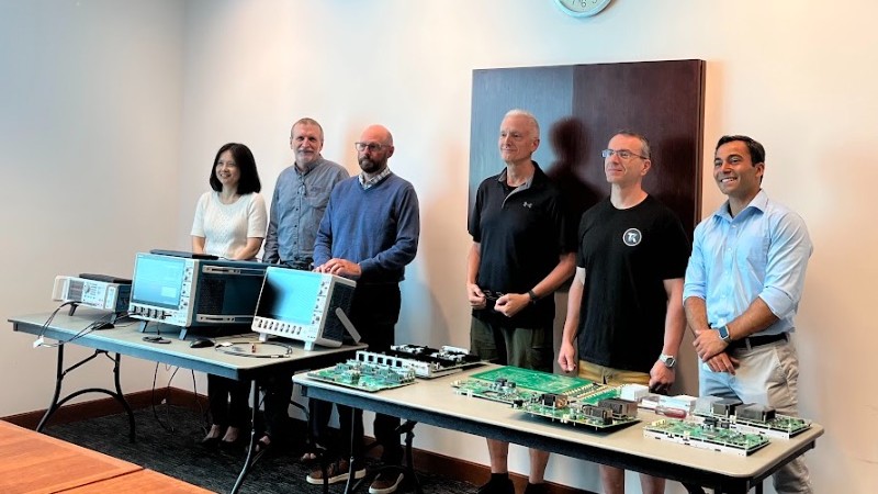
The engineers behind the 7 Series. Left to right: Jenny Yang, Software Engineering Manager, Forrest Edwards, Program Manager & Principal Engineer, Mark Briscoe, Senior Product Planner & Product Marketing, Tim Bieber, Principal Product Planner, Gene Markozen, Hardware / Software Design Engineer IV at Tektronix Core Real Time, and Jake Hertz, All About Circuits contributor.
Tektronix engineers shared a notable anecdote where a single mechanical change unlocked a breakthrough for the entire product. Early prototypes tried to fit twice the circuitry by laying acquisition boards parallel to the front display. Power supplies quickly spilled off the board, and airflow simulations showed hot spots that couldn’t be cooled.
The simple act of rotating the boards perpendicular to the display gave mechanical engineers room for larger cooling plenums and allowed electrical engineers to reroute power and signal paths cleanly. “Seriously, once we rotated the boards, it was like a logjam became unclogged,” recalled hardware lead Gene Markozen.
Customer requests also feed into this cycle. The engineers described another instance where a defense lab requested the new product feature an ultra-low-latency trigger, but the digital-only design had microsecond delays. Adding such a feature risked rearchitecting the entire signal path.
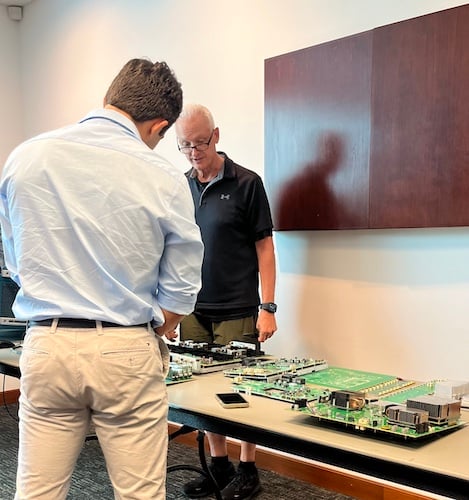
Jake Hertz (blue) inspecting Tektronix PCBs with Tim Bieber (black).
The compromise came when engineers proposed reintroducing an analog trigger chip from a previous generation. “That worked out well because not only did we end up getting an analog trigger…but we also got two free amplifiers out of that chip,” said Forrest Edwards, Program Manager & Principal Engineer. Firmware and software teams then integrated the dual-path logic into the user interface. What started as a late-stage concern evolved into a feature that spanned hardware, firmware, and software without derailing the entire system.
The truth is that no singular specification arrives on a datasheet fully formed. Each exists because dozens of teams worked through loops of dependency, compromise, and invention. And, along the way, there are thousands of microdecisions that collectively determine whether the instrument performs as promised.
Staying Aligned
With literally hundreds of engineers contributing, alignment is the only way to make progress. Tektronix relies on a structured but flexible engineering flow that turns thousands of individual tasks into a coherent oscilloscope.
It begins with clear documentation. “We have a product requirements document, and the 7 Series had well over a thousand requirements,”Mark Briscoe, Senior Product Planner & Product Marketing, explained. That Product Requirements Spec (PRS) acts as the contract between marketing and engineering, defining what the instrument must deliver.
From it comes the Engineering Instrumentation Spec (EIS): what several team members described as the “Bible.” “That’s the document we all agree to, because it’s the basis for what we’re building,” Briscoe added.
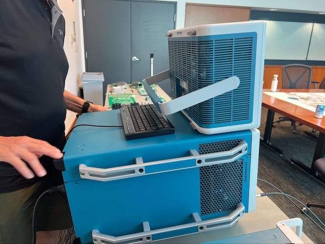
The size difference of the 6 Series scope (top) compared to the 7 Series scope (bottom) indicates just how much has changed between the generations.
The PRS says what the scope must do, while the EIS details how good it must be. But nothing is set in stone, and these specs evolve over time as more data from prototypes and testing is collected. If a metric proves unattainable, the spec may be adjusted. If it’s too central to compromise, the team may go back and redesign.
To keep everyone synchronized, Tektronix runs weekly core team meetings. “We’re a matrix organization, so we have the leads sit on the core team. That’s how everybody comes together once a week and hashes through all the trade-offs,” Tim Bieber, Principal Product Planner, explained. Build-measure-learn cycles guide whether the project is on pace or needs more resources.
Culture and Collaboration
Beyond specifications and processes, what stood out was the culture of the team itself. Many of the engineers working on the 7 Series have spent decades at Tektronix, some 20, 30, or even 50 years. That kind of continuity has created an environment where institutional knowledge accumulates and collaboration becomes second nature.
“It takes about five years to really learn the business, and once you do that, you realize how fundamental this work is,” said Bieber.
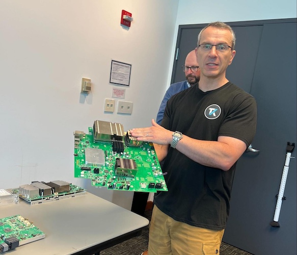
Gene Markozen holding a PCB.
Markozen put it more bluntly: “It’s amazing what you can get done if you don’t care who gets the credit.” In practice, that attitude shows up when unexpected requests or failures surface late in development. Instead of pushing responsibility elsewhere, engineers describe huddling across disciplines to find a solution.
The result is less about a polished process and more about instinctive problem-solving. A project as complex as the 7 Series doesn’t hold together simply because of documents and specs. It works because the people behind it have built a culture of shared ownership over decades.
Beyond the Waveform
The story behind the 7 Series makes clear that these instruments are anything but neutral in how they come to be. They are the product of thousands of microdecisions, cycles of dependency between disciplines, and a culture shaped over decades.
What Tektronix’s engineers described was less a neat process and more a kind of controlled chaos: documents that evolve as prototypes teach new lessons, meetings where priorities are renegotiated, and late-breaking customer requests that send engineers back to the board just days before a design freeze.
“When you finish, you look back and say, ‘Why would you do it any other way?” says Bieber, “But the truth is, it looked nothing like this at the beginning.”
The next time an engineer fires up a scope and sees a clean eye diagram or a perfectly flat frequency sweep, it’s worth remembering the invisible work behind the display.
All images taken by All About Circuits.
Related Content