Facebook
 Google
 GitHub
 Linkedin
Get Out of My Space! PCB Keepout Areas in the Z-Axis
In this article, we'll discuss the importance of PCB enclosure design by considering enclosure design.
PCB keepouts don't just exist on a board, itself. When it comes to giving components the space they need, how does a design team consider the z-axis?
In my previous article, I talked about PCB keepout areas and why they're important. But PCB keepout areas don't just refer to the board, itself. A keepout area could also include the enclosure it lives in, which needs to be able to protect the PCB inside, even under stress. So how can we prevent an enclosure from encroaching on the z-axis of a PCB?
Again referring to my last article, I mentioned that I've identified two methods to effectively implement PCB keepouts in PCB design. The first I recommended was 3D modeling to give you the opportunity to foresee issues before fabrication.
The second method is to communicate effectively to all team members regarding all design changes and to have an open mind regarding members’ comments and/or feedback. This only works, of course, if you have a fully staffed team including a systems engineer, test engineer, PCB layout designer, design/electrical engineer, mechanical engineer, and of course assembly technicians. Getting all team members in one room—yes, a design review meeting!—to discuss the design openly will be most effective and beneficial. This becomes exceptionally important when working with enclosures.
So let's take a look at how we could approach the analysis of an enclosure and how it relates to keepout areas.
Enclosure Analysis
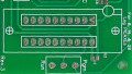
Let's consider an SSD sheet metal enclosure as seen in the figure below.

SSD enclosure example. Image courtesy of Samsung
Less sheet metal material equates to less money, right? True, but at what point does the sheet metal become too thin? To get the right (scientific) answer, as opposed to guessing, we should ask our mechanical engineer team member to model the SSD enclosure and to also provide stress analysis for various sheet metal thicknesses. The goal here is to determine at which thickness the sheet metal deflects far enough to come into contact with the underlying electrical components. If the sheet metal were to directly come into contact with capacitors, for instance, sparks may fly!
According to Andy Johnston, of Johnston Engineering, "Structural analysis is an important part of the product development cycle when you have parts or assemblies that need to be strong enough to resist applied loads. Finite Element Analysis (FEA) is one tool used in structural analysis to model the stresses and strains of materials under applied loads such as forces, torques, or from thermal expansion. FEA allows the mechanical engineer to predict how the SSD assembly will react to applied loads and verify the structural fitness of the design before a prototype is ever fabricated."
What might this analysis look like? Let's walk through the process.
An Example Sheet Metal Enclosure Analysis
To help demonstrate sheet metal stress analysis, I have used a study, provided by Johnston Engineering, to illustrate how sheet metal deflection occurs as a function of material thickness. In this study, it is assumed that when a person squeezes the SSD, 5 lbs of force is applied to the enclosure—it is common and expected for an SSD to be squeezed during the installation process.
Assumptions:
- A 5 lb load is applied to each side in an oval shape in the middle of the external case.
- The screw holes in the cover and the top surface of the PCB are fixed geometrically (meaning they don’t move).
- See Figures 4 and 5.

Figure 4. 3D model of an SSD (solid-state drive). Image courtesy of Johnston Engineering.

Figure 5. A 5 lb load applied to the enclosure. Image courtesy of Johnston Engineering.
Analysis Scenario #1:
-
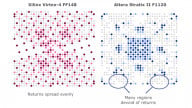
Using a 0.020” thick sheet metal cover, there is initially 0.060" clearance between the capacitors and the metal cover. The displacement plot (Figure 6) shows the 5 lb force resulting in a 0.078” displacement, meaning the capacitors contact the cover.

Figure 6. A 5 lb load applied to a 0.020" thick cover results in the cover touching the capacitors on the PCB. Image courtesy of Johnston Engineering.
Analysis Scenario #2:
-
Using 0.040” thick sheet metal, there is 0.040” initial clearance between the capacitors and the enclosure. Applying the same 5 lb load only results in a 0.010” displacement, meaning there is still 0.030” of clearance—the cover does not touch the capacitors (see Figure 7).

Figure 7. A 5 lb load applied to a 0.040" thick cover. The cover does not contact the capacitors. Image courtesy of Johnston Engineering.
Therefore, when you want to minimize sheet metal material cost and maintain your desired PCB keepout area on the Z-axis, a 0.040" thick cover would be a better choice than a 0.020" cover. This will ensure that no electrical shorting occurs when a person squeezes the SSD using a 5 lb force.
In Summary
When designing a PCB it may be easy, or tempting, to overlook PCB keepout areas. Such keepout areas, however, are crucial for upholding a reliable design. To help guarantee that PCB keepout areas are properly maintained, it would behoove you to employ a mechanical design engineer who is capable of producing 3D models and performing stress analysis. And finally, effectively communicating with team members helps to prevent violations of PCB keepout areas and thereby reduces the time, money, and energy needed for designing and manufacturing revised PCBs.