Facebook
 Google
 GitHub
 Linkedin
How Do You Reduce EMI in DC-DC Power Management?
Selecting the right switching DC-DC step-down regulator while minimizing EMI can feel like a balancing act. Here's an idea of how to do it with ADI's new integrated regulator.
In electronic systems and device designs, developers will always encounter electromagnetic interference (EMI). Selecting the right switching DC-DC step-down regulator while minimizing EMI can feel like a balancing act.
In this article, we'll discuss what EMI is and how to reduce EMI in power management circuits using Analog Device's new integrated regulator as a use case. We'll also see how this particular DC-DC step-down regulator holds up against others like it around the industry.
What is EMI?
EMI is a form of energy generated from a switching power supply and other sources. Not only will untamed EMI interfere with other electrical equipment; it violates FCC regulations.
In an environment in which circuitry, modules, and components are nearby, sensitive communication design, such as RF and other audio designs, are affected by this EMI electrical noise.
Electronic devices and designs using a 5 V DC are very common in applications like automotive, telecommunications, industrial, medical, computing, and military. Often a circuit will derive the needed 5 V input from a system power source using a step-down voltage regulator to do the conversion from a higher voltage source.

Radiated EMI performance and conducted EMI performance of LT8648S. Image used courtesy of Analog Devices
However, switching regulators can easily generate EMI emission through conduction or radiation. The conducted EMI emission follows the wires and printed circuit board (PCB) traces to affect the product circuitry.
Radiated EMI emission is generated from the circuit as a whole but, unfortunately, cannot be fully tested until the whole printed circuit assembly (PCB with components fully populated) is completed. It is costly to do a re-layout of the PCB should it fail the EMI test.
To learn more about two different types of EMI, check out Robert Keim's article on the difference between conducted and radiated EMI.
How to Reduce EMI in Power Management Circuits
To reduce EMI from the switching regulator, a developer can add external discrete circuitry or metal shielding. The designer could also use an integrated regulator (like Analog Device's new LT8648S) to accomplish the voltage step down with reduced EMI.
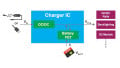
The LT8648S, a synchronous step-down DC-DC regulator, is based on a second-generation proprietary silent-switcher architecture with an internal bypass capacitor to reduce radiated EMI. The capacitor will absorb excess EMI current (in a charging mode). Additionally, a developer can further reduce EMI using the suggested PCB layout by adding two small one microfarad capacitors placed near the regulator.

Typical application of the LT8648S. Image used courtesy of Analog Devices
The regulator accepts input voltages from 3 V to 42 V and supports an output current from 1 A to 15 A suitable for applications in automotive, industrial and communications systems. It can achieve high conversion efficiency at a high frequency (up to 95.5% efficiency at 1 MHz, 12 VIN to 5 VOUT and up to 93% efficiency at 2 MHz, 12 VIN to 5 VOUT ), which helps pass the CISPR 25 class 5 peak EMI limits.
Additionally, the regulator can be programmed to operate in four different modes by connecting pin 32 differently.
- Burst mode operation: tie the pin to ground, which will allow low quiescent (standby) current consumption
- Forced continuous mode (FCM): leave this pin floating—not connected to anything—to enable a fast transient response and control the frequency harmonics
- Spread spectrum mode: tie the pin to high or greater than 3 V to further reduce EMI emissions
- Synchronous mode: connect the pin to an external clock, which will synchronize with the source and operate in FCM
The regulator comes in a 36-lead 7 mm × 4 mm LQFN package.
How Does LT8648S Fare on the Step-Down Regulator Stage?
A quick survey of DC-DC step-down regulators on the market will show there are many selections with different parameters.
Some have the right voltage, but the output current is small (less than 1 A for the TI TPS62000 family). Maxim offers the uSLIC family with variable output voltage, but its maximum output current is 2 A. Pololu provides another model with an output of 5 V and 15 A, but its size is large (Pololu D24V150F5 is 43 mm x 31 mm compared with LT8648S, which is 7 mm x 4 mm).
If you are looking for high-output current support, TI’s TPS546D24A DC-DC regulator offers an output current of 40 A (cascade 4 to deliver 160 A), but input voltage is limited to 3 V to 16 V. Its package size of 7 mm x 5 mm is comparable to the LT8648S.

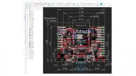
LT8648S pin configuration and package size. Image used courtesy of Analog Devices
Current and voltage aside, there is the EMI compliance issue to deal with. The LT8648S can help address the EMI compliance issue with an integrated capacitor and still fits in a very small package. It also has an operating temperature range of -40°C to 125°C, which exceeds most commercial-grade solutions.
If you are looking to tame EMI, the LT8648S may offer a good solution.
What are some other ways you manage EMI in your designs? Share your experiences in the comments below.
Related Content