Facebook
 Google
 GitHub
 Linkedin
PCB Design Considerations When Using Bi-Directional Translators
In the past, we touched on the theoretical underpinnings of voltage-level translators. Now, we'll discuss some practical design tips for using these increasingly-common devices in your design.
In a previous article, we discussed the place of voltage-level translators in a world of varying voltages. Beyond their theory of operation, these translators must be put into circuits carefully.

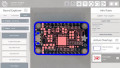
Application diagram using voltage-level translators. Image used courtesy of Texas Instruments
The devices that a translator connects to can greatly influence design considerations when placing them on a PCB. According to an ON Semiconductor application note, there are three main phenomena that will affect PCB design when using bi-directional translators: power supply decoupling, RF susceptibility/radiated emissions, and required ESD and EMI protection.
In this article, we'll review some design guidelines when using voltage translators, which are becoming increasingly common across electronics applications.
Power Supply Decoupling
First, power supply noise can kill a bi-directional translator's functionality. Drastic changes can indicate a logic change to the bus-hold circuit and erroneously switch the direction of the input and output.
Also, digital communication and power supply noise never mix well with one another, since power supply noise can affect the digital lines and cause a command/response to become distorted. The best way to fix this is to place decoupling capacitors, specifically ceramic capacitors in the range of 0.01uF to 1uF, to bypass the AC noise on the power line.
These capacitors may be the most useful solution because of their high-frequency characteristics. They act as a short to ground for these AC signals, thus leaving the DC power supply voltage alone. Designers must place these capacitors as close to the chip as possible and ground them properly to ensure maximum efficacy, an example of which is shown below:

By placing the capacitors close to the VL and VCC power pins, effective power supply decoupling occurs. This also provides a low-impedance ground connection. Image used courtesy of ON Semiconductor
RF Susceptibility and Radiated Emissions
From the above figure, we can see the capacitors grounded via a ground plane. This is, perhaps, one of the most effective methods of grounding in order to avoid loops, which can minimize the second phenomenon of RF susceptibility.
Furthermore, the application note states that these translators must be connected with traces that minimize loops. Loops are formed with a signal/power trace and a ground trace, and the larger the loop, the more antenna characteristics that it exhibits. The figure below shows the loops formed due to a poorly-designed PCB layout.

The longer the PCB trace, the higher the RF susceptibility. Image used courtesy of ON Semiconductor
The loops in the figure can be minimized by decreasing the length of the I/O1 and I/O2 traces by moving the translator as close as possible to the I/O connector and connecting the I/O connector and the translator to ground via a ground plane. These changes will shrink loop area, thus cutting RF emissions while maximizing its efficiency. The resulting layout may look similar to this one:

Image used courtesy of ON Semiconductor
ESD and EMI Protection
Because the translator can be connected to internal and external devices, safety is crucial to its operation. Since so many applications that require a voltage translator involve a connection to an external signal, these devices are usually designed to withstand a certain surge level, including certain ESD protections.
Oftentimes, these capabilities are not enough for external connection applications and thus require some added protection.
Transient Voltage Suppressor Diodes
Transient voltage suppressor (TVS) diodes can be a solution. TVS diodes, according to Semtech, are solid-state PN junction devices that are used to protect sensitive ICs from transient surges. Under normal operation, they act as open circuits, minus some leakage. When a certain threshold voltage is detected, it avalanches and becomes a short.

Operation of a TVS diode. Image used courtesy of Semtech
These devices can be unidirectional or bidirectional in nature, and more often than not bidirectional ones are used. TVS diodes should be connected to an EARTH/CHASSIS ground connection rather than the circuit’s signal ground signal. This implementation is useful to avoid any “ground bumps” because these surges disturb your ground signal, which can have devastating effects on the entire circuit operation.
Additionally, Semtech recommends that designers place the TVS diodes close to the source of the external signals going into the translator. They must be grounded via a plane (ideally), or have very short “stub” connections to their grounded side in order to maximize their effectiveness. An example of a best-case-scenario layout of these diodes is shown below:

The performance of voltage-level translators can be enhanced by considering the layout of I/O traces, TVS diodes, and decoupling capacitors. Image used courtesy of ON Semiconductor
If these guidelines are followed, the operation of the translator will be near guaranteed and the safety of the device is maximized.
Related Content