 Facebook
 Google
 GitHub
 Linkedin
Qualcomm Creates New Bulk Acoustic Wave Filter to Cover C-Band
Qualcomm’s new BAW filter for the C-band complements its existing SAW filter technology. Qualcomm’s portfolio now differentiates frequencies from 600 MHz to 7.2 GHz.
Filter technology is a critical element in the RF signal chain that allows for signal selectivity. Surface acoustic wave (SAW) and bulk acoustic wave (BAW) are two types of electromechanical filters using piezoelectric transduction for channel selection in modern radio receivers.
Last week, Qualcomm announced a new filter solution, the ultraBAW RF filter. The ultraBAW is intended to differentiate signals from 2.7 GHz up to 7.2 GHz, enabling new solutions for 5G and Wi-Fi.
Qualcomm’s ultraBAW, along with its ultraSAW technology, creates a filter solution covering a large portion of the radio spectrum. These filters add to the portfolio of RF solutions by Qualcomm including its modem-to-antenna RF system.

Qualcomm filter solution frequency coverage. Image used courtesy of Qualcomm
In this article, we will overview the differences between the SAW and BAW filter technologies. Then we will break down the Qualcomm BAW filter solution announcement and examine the proposed benefits of this new technology.
What’s the Difference Between SAW and BAW Filters?
Fundamentally, SAW and BAW filters operate by transducing an electrical signal into a piezoelectric material that vibrates at some given natural frequency. This natural vibration carries only a subset of frequencies from the input to the output transducer, which (ideally) returns the desired set of signals into the electrical domain.
A surface acoustic wave filter transduces the signal laterally along the surface of the piezoelectric material from one interdigital transducer to another.

Artistic description of the structure of a SAW filter. Image used courtesy of OnScale
Conversely, a bulk acoustic wave filter transduces the signal vertically through the piezoelectric material in between two electrodes.

Artistic description of the structure of a BAW filter. Image used courtesy of OnScale
There are two main designs for BAW resonators: FBAR (thin-film bulk acoustic wave resonator) and SMR (solidly mounted resonator). The FBAR is designed with a cavity below the support substrate and must be carefully designed to reduce boundary leakage of the device. Meanwhile, the SMR uses Bragg layers as an acoustic reflector to help reduce leakage inside the substrate.

FBAR and SMR BAW topologies. Image used courtesy of Sun et al.
An Overview of 5G BAW Design Challenges
There are several 5G-related design challenges that necessitated an improved acoustic filter technology. Higher frequencies (up to 7 GHz) are chief among the list of concerns. Higher frequencies offer increased bandwidth, but designing a filter to support wide bandwidths with appropriate out-of-band rejection is a key challenge.
5G radio systems also deal with tighter link budgets, which require lower insertion loss filters. Additionally, as filters become smaller and more integrated, heat dissipation becomes the second key challenge.
Bulk Acoustic Wave (BAW) Configurations and Parameters
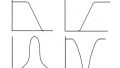
There are two general configurations for a BAW filter: ladder or lattice. These two configurations can combine to create a hybridized structure that creates a third electrical passband response. Generally speaking, ladder-type BAW has poor out-of-band rejection, which makes it less than ideal for channelized radio.

The three general configurations of a bulk acoustic wave filter. Image used courtesy of Qorvo
The key figure of merit (FOM) for BAW resonators is the effective coupling coefficient squared (Keff2) and the Q-factor of the filter. Keff2 affects the available bandwidth of the filter with a higher value providing greater bandwidth. The value for the effective coupling coefficient is given by the series and parallel resonant frequencies.
\[Keff^2 =\frac{\pi^2}{4} \cdot \frac{fs}{fp} \cdot \left( \frac{fp-fs}{fp}\right)\]
The fundamental frequency (f0) of the filter is proportional to the acoustic velocity and inversely proportional to twice the thickness of the piezoelectric material. Additionally, the thickness of the electrodes can affect the fundamental frequency shift.
Pushing the frequencies of operation up to 7 GHz results in shrinking geometries. The electrode material requires optimized orientation, low surface roughness, and low lattice distortions relative to the piezoelectric layer to ensure solid performance.
Qualcomm’s ultraSAW and ultraBAW Filters
Released in early 2020, the ultraSAW filter technology covers frequencies from 600 MHz to 2.7 GHz. The advancement in SAW technology was said to bring excellent cross isolation along with high-frequency selectivity, very low insertion loss, and improved temperature stability.

Applications for Qualcomm’s ultraSAW technology. Image used courtesy of Qualcomm
Fast-forwarding to late 2021, the ultraBAW technology covers 2.7 GHz to 7.2 GHz. It is said to address many of the concerns related to filtering the C-band including support for 300 MHz channels and the coexistence of Wi-Fi 5 GHz and 5G New Radio (NR). ultraBAW is also housed in a small package and is designed to address thermal concerns.

Tackling C-band radio applications with ultraBAW. Image used courtesy of Qualcomm
The ultraBAW and ultraSAW are just a part of the radio solutions portfolio from Qualcomm. The portfolio also includes power amplifier modules, diversity modules, Wi-Fi, and discrete filters. While Qualcomm is focused on the emergent 5G market, it envisions its RFFE product portfolio addressing many market segments including automotive, PCs, IoT, and industrial applications.
Do you have design experience related to SAW and BAW filter technology? What parameters were the biggest constraints? Let us know in the comments below.


I would like to simulate Qualcomm SAW filters B2611 and B2618 (B39162B2611P810, B39162B2618P810) in LTspice but Qualcomm does not provide SPICE models and refused to me provide support.