 Facebook
 Google
 GitHub
 Linkedin
An Introduction to Filters
Learn about various types of filters, including common terminology and important characteristics.
Not sure where to start with reading about filters? This article will help you get more familiar with filters and introduce a number of All About Circuits textbook resources for further study.
What Is a Filter?
A filter is a circuit capable of passing (or amplifying) certain frequencies while attenuating other frequencies. Thus, a filter can extract important frequencies from signals that also contain undesirable or irrelevant frequencies.
In the field of electronics, there are many practical applications for filters. Examples include:
-
Radio communications: Filters enable radio receivers to only "see" the desired signal while rejecting all other signals (assuming that the other signals have different frequency content).
-
DC power supplies: Filters are used to eliminate undesired high frequencies (i.e., noise) that are present on AC input lines. Additionally, filters are used on a power supply's output to reduce ripple.
-
Audio electronics: A crossover network is a network of filters used to channel low-frequency audio to woofers, mid-range frequencies to midrange speakers, and high-frequency sounds to tweeters.
-
Analog-to-digital conversion: Filters are placed in front of an ADC input to minimize aliasing.
Four Major Types of Filters
The four primary types of filters include the low-pass filter, the high-pass filter, the band-pass filter, and the notch filter (or the band-reject or band-stop filter). Take note, however, that the terms "low" and "high" do not refer to any absolute values of frequency, but rather, they are relative values with respect to the cutoff frequency.
Figure 1 below gives a general idea of how each of these four filters works:
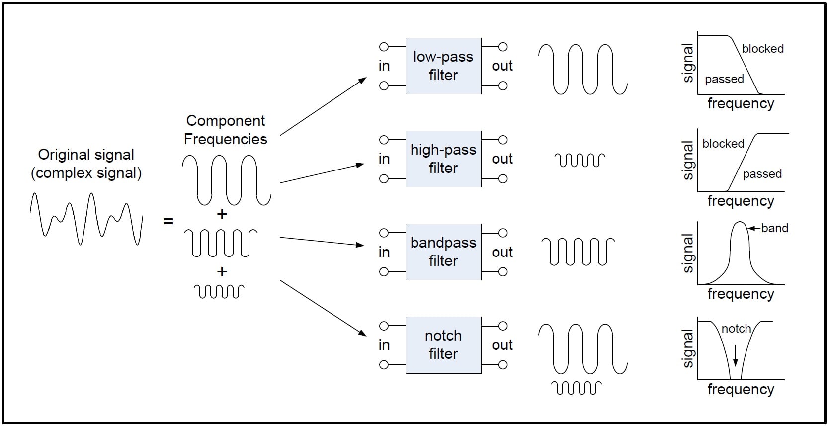
Figure 1. A basic depiction of the four major filter types.
There is also such a thing as an all-pass filter, but I'm not considering it to be one of the four basic filter types for this article.
Passive and Active Filters
Filters can be placed in one of two categories: passive or active.
Passive filters include only passive components—resistors, capacitors, and inductors. In contrast, active filters use active components, such as op-amps, in addition to resistors and capacitors, but not inductors.
Passive filters are most responsive to a frequency range from roughly 100 Hz to 300 MHz. The limitation on the lower end results from the fact that the inductance or capacitance would have to be quite large at low frequencies. The upper-frequency limit is due to the effect of parasitic capacitances and inductances. Careful design practices can extend the use of passive circuits well into the gigahertz range.
Active filters are capable of dealing with very low frequencies (approaching 0 Hz), and they can provide voltage gain (passive filters cannot). Active filters can be used to design high-order filters without the use of inductors; this is important because inductors are problematic in the context of integrated-circuit manufacturing techniques. However, active filters are less suitable for very high-frequency applications because of amplifier bandwidth limitations. Radio-frequency circuits must often utilize passive filters.
Some Key Points and Terms
Response curves are used to describe how a filter behaves. A response curve is simply a graph showing an attenuation ratio (VOUT / VIN) versus frequency (see Figure 2 below). Attenuation is commonly expressed in units of decibels (dB). Frequency can be expressed in two forms: either the angular form ω (units are rad/s) or the more common form of f (units of Hz, i.e., cycles per second). These two forms are related by ω = 2πf. Finally, filter response curves may be plotted in linear-linear, log-linear, or log-log form. The most common approach is to have decibels on the y-axis and logarithmic frequency on the x-axis.
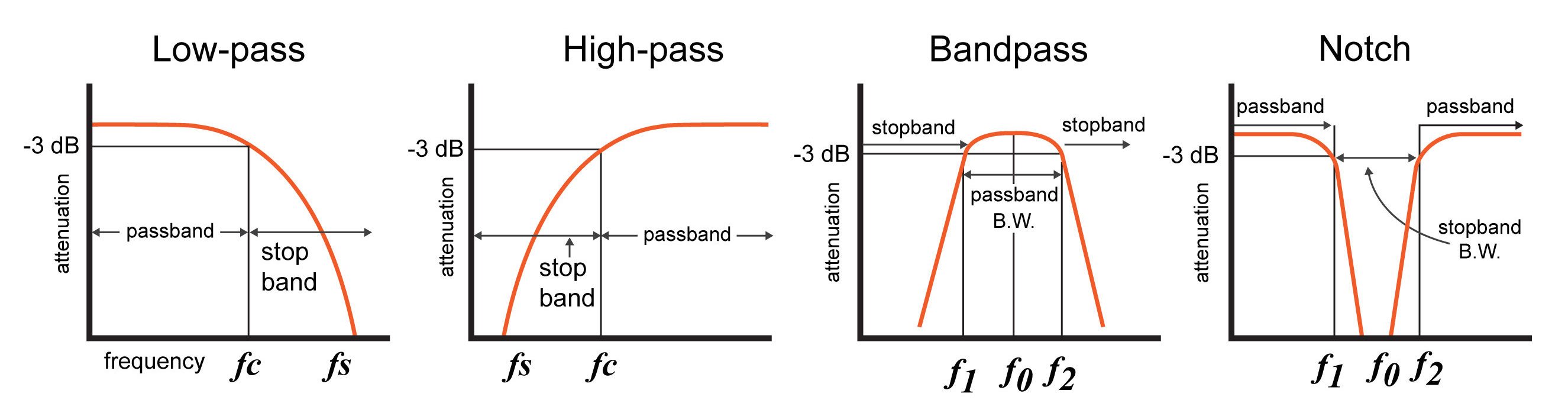
Figure 2. Response curves for the four major filter types.
Note: A notch filter is a bandstop filter with a narrow bandwidth. Notch filters are used to attenuate a narrow range of frequencies.
Below are some technical terms that are commonly used when describing filter response curves:
-
-3 dB frequency (f3dB). This term, pronounced "minus 3dB frequency", corresponds to the input frequency that causes the output signal to drop by -3dB relative to the input signal. The -3 dB frequency is also referred to as the cutoff frequency. It is the frequency at which the output power is reduced by one-half (which is why this frequency is also called the "half-power frequency"), or the output voltage is the input voltage multiplied by 1/√2. For low-pass and high-pass filters, there is only one -3 dB frequency. However, there are two -3 dB frequencies for band-pass and notch filters—normally referred to as f1 and f2.
-
Center frequency (f0). The center frequency, a term used for band-pass and notch filters, is a central frequency between the upper and lower cutoff frequencies. The center frequency is commonly defined as the arithmetic mean (see equation below) or the geometric mean of the lower and upper cutoff frequency.
-
Bandwidth (β or B.W.). The bandwidth is the width of the passband, and the passband is the band of frequencies that do not experience significant attenuation when moving from the input of the filter to the output of the filter.
-
Stopband frequency (fs). This is a particular frequency at which the attenuation reaches a specified value.
-
For low-pass and high-pass filters, frequencies beyond the stopband frequency are referred to as the stopband.
-
For band-pass and notch filters, two stopband frequencies exist. The frequencies between these two stopband frequencies are referred to as the stopband.
-
-
Quality factor (Q): The quality factor of a filter conveys its damping characteristics. In the time domain, damping corresponds to the amount of oscillation in the system’s step response. In the frequency domain, higher Q corresponds to more (positive or negative) peaking in the system’s magnitude response. For a bandpass or notch filter, Q represents the ratio between the center frequency and the -3dB bandwidth (i.e., the distance between f1 and f2).
-
For both band-pass and notch filters:
-
$$Q =\frac{f_0}{f_2 - f_1}$$
Conclusion
Filters serve a critical role in many common applications. Such applications include power supplies, audio electronics, and radio communications. Filters can be active or passive, and the four main types of filters are low-pass, high-pass, band-pass, and notch/band-reject (though there are also all-pass filters).
I hope you've learned a bit about how to describe filters and what they can accomplish. You can read more in these textbook resources below!
Related Content


Thank you…
This is so Helpful