Facebook
 Google
 GitHub
 Linkedin
Sending ICs to Space: An Isolated Error Amplifier from Analog Devices
The ADuM3190S is an isolated error amplifier intended for use with linear feedback power supplies. The transfer function of this device is stable over a wide temperature range and over the lifetime of the device.
What is an error amplifier? How do we test components for use in space? In this article, we'll take a look at a recent isolated error amplifier from Analog Devices and try to answer these questions along the way.
The Analog Devices AduM3190S is an isolated error amplifier that provides fast transient response for linear feedback power supplies. The datasheet states that it is designed to provide better transient response, power density, and stability than optocoupler or shunt-regulator solutions. It is intended for use with linear feedback power supplies. The transfer function of this device is stable over a wide temperature range and over the lifetime of the device. Let's take a closer look
What Is an Error Amplifier and Why Do I Need One?
There are many ICs that allow designers to convert from one DC voltage to another. Negative feedback is a fundamental technique in voltage regulation because it allows the regulator to establish a certain output voltage and maintain this voltage despite changes in load current. The error amplifier is the central component in this negative-feedback system: it compares the output voltage to a known reference and thereby generates an error signal that allows the circuit to make the necessary corrections.

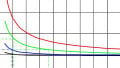
Image of output ripple from TI
Switching regulators typically work by temporarily storing energy in the magnetic field of an inductor. Inductors oppose changes in flux and establish currents to maintain magnetic flux. Charges rush into and out of these storage devices and the changing potentials are filtered through a capacitor that ultimately provides the constant potential difference and current requirements of the output. A switching regulator must decide when to turn on and off to control the inrush/outrush of charges and regulate the output. Thresholds are established above and below the desired output voltage. As the switching circuit oscillates between these two thresholds, a “ripple” is seen on the output. This ripple introduces noise downstream that can affect the accuracy of analog-to-digital converters and create electromagnetic interference.
Error amplifiers intercept the output voltage and compare it to a stable voltage reference. As the output of the switching regulator varies above or below the target voltage, the error amplifier produces a larger potential difference that very quickly turns the switching regulator on and off. The result is that the switching regulator overshoot and undershoot are strictly controlled and reduced by several orders of magnitude.
What is Inside the IC?
Let's take a look inside the ADuM3190 IC:

Error amplifier pinout from datasheet
Many error amplifiers use optocouplers or shunt regulators—this amplifier does not. Instead, it uses an isolation transformer to transfer digital signals to couple the circuits on either side of the IC. An op-amp on the right side of the device is meant to connect to a voltage divider that is connected to the output of the device.
The error signal is digitized and transmitted through the Tx block through the transformer to the Rx block. On the left side of the device, the Rx block decodes the PWM signal sent by the right side and uses the information to drive the error amplifier output pins on the left side of the block. For a more detailed description, please see the datasheet.
How Do You Prepare an IC for Space?
This IC started life as the ADuM3190 error amplifier. It wasn’t until they sent it down to the University of Texas for space certification that it became the proud ADuM3190S that stands before you today. Space isn’t very far away in aerospace terms, but it is a very harsh environment with different engineering rules.
If your chip runs into a small meteor at orbital speeds, you are just plum out of luck. Nothing will survive a 108,000 km/hr impact with a marble-sized meteor. Other problems are a bit more subtle. For example, cooling—an IC in orbit around the Earth cannot depend on convective cooling. It must rely on conduction or radiative cooling. Fortunately, thermal engineers have dealt with these problems for decades and they can provide advice.
Once you leave the atmosphere, there is a large amount of radiation that your device must contend with. And this is the type of ionizing radiation that strips electrons from atoms and shortens the lifespans of astronauts. The only way to know how the device will perform is to bombard it with the same type of radiation down here on the surface of the earth through ion bombardment.

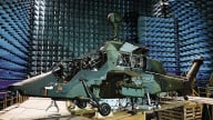
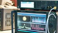
Ion bombardment test setup, modified for clarity.
The ADuM3190 was certified at the Cyclotron Institute at Texas A&M University. Six of the ICs were subjected to as much as $$10^7 \frac{\text{ions}}{\text{cm}^2}$$ at a temperature of 125 °C to attempt to force a latch-up condition. The results are listed on page 9 of ADuM3190S datasheet. To my amazement, most of the ICs under test worked after the ion bombardment.
Evaluation Board Available
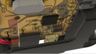
The CN0342 is a flyback power supply that uses the ADuM3190 error amplifier to provide a feedback signal from the secondary side to the primary side of the flyback transformer. The demonstration circuit is able to provide up to 1 A output with a 5V output configuration and can tolerate input voltages that range from 5V to 24 V.

CN0342 EVM from Analog Devices
Conclusion
If you are going to send a sensor to space, make sure that it has a stable power supply. Error amplifiers are a crucial part of a switching regulator’s feedback loop and help the regulator to provide a low-noise, highly accurate reference.
Have you had a chance to use an error amplifier in one of your designs? Do you have experience with preparing components for the harsh conditions of space? We’d love to hear about it. Leave a comment below.
Related Content