 Facebook
 Google
 GitHub
 Linkedin
Teardown Tuesday: Induction Cooktop
In this Teardown Tuesday, we are going to look at the insides of an induction cooktop!
Ever wonder what components make an induction cooktop work? We'll find out in this week's Teardown Tuesday.
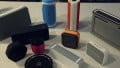
Induction cooktops are a popular alternative to electric and gas cooktops because they offer higher efficiency than their alternatives. This appliance contains two circuit boards, an induction coil, and a pair of temperature sensors. Compared to many of today's electronics, this cooktop is very modular and repairable.

The cooktop
Opening It Up
To open up the induction cooktop, eight self-tapping Phillips head screws had to be removed. Once these were out, the plastic shell separated into two pieces. The first piece, the top, includes the user interface and associated electronics. The bottom piece is the glass cook top. Connecting the two layers is a five-position ribbon cable.

The cooktop with the top off
UI Electronics

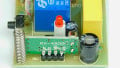
The user interface PCB
These electronics allow the user to control the cooktop. The UI electronics are comprised of a circuit board with all of the UI elements on it. The board is populated with seven 5mm red led lights, six tactile buttons, and a seven-segment display. The board does have footprints for two additional tactile buttons and two more leds, but these are unpopulated.

The 1628 LED driver
On the back of the board is there a “1628” led driver. The 1628 LED driver is manufactured by multiple companies and does a whole lot more than just control LEDs. The 1628 converts serial data into individual LED controls and allows for the scanning of buttons. This driver is in a SOP 28 package and is soldered to the rear of the one-layer PCB.
.jpg)
The component side of the UI PCB
The PCB has a few other passive components located on the top. These components perform a logic level conversion using a voltage divider network and help filter the signals.
Power Supplies

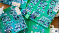
The bottom circuit board
Located in the lower half of the opened enclosure, a second circuit board handles the voltage regulation and device control. This is a single-sided board with a handful of jumper wires and components on both sides. The solder side of the board is coated with a conformal coating to protect the small surface-mount components.

Small surface-mount components
The AC power coming into this circuit board is split into two paths. There is a higher-power path that powers the induction coil and a lower-power path that powers control electronics.
The 120V is connected through a pair of spade connectors. The 120V is then passed through a 250V 20A fuse. A Thinking TVR 07241 protection varistor is across the input to protect the electronics.
Following the lower-power path, there are four diodes that form a bridge rectifier. An AC-to-DC converter then converts the voltage to XVDC. This conversion is controlled with the aid of an STMicroelectronics VIPER12A and a switch mode transformer with an EE13 core. The AC-to-DC converter operates at a fixed 60kHz.

The low-power switching power supply

The high-power switching power supply IGBT
The high-power electronics also go through a bridge rectifier, albeit a higher-power heatsink-mounted one. The full wave rectified voltage is then sent through two large inductors, L1 and L2, and then smoothed by C2 and C3. The two IGBT in parallel, Q1 and Q10, switch the voltage to the coil. The two transistors are Infineon IHW20N120R3 and are rated for 40A at 1200V.
Control Electronics

The specialty microcontroller
At the heart of this device is a special microcontroller, an S3F84B8 made by Zilog. This microcontroller is designed for use in induction cooktops!
This microcontroller has a few features that make it advantageous for this use. It features a 10-bit PWM channel to switch the coil, eight 10-bit analog-to-digital converters. It required few external components, reducing BOM cost.
Coil

The induction coil
The key part of the induction cooktop is the coil. The coil in this induction cooktop measures is comprised of 21 turns of Litz wire. The multi-conductor Litz wire is used to reduce the skin effect.

The Litz wire
Located in the middle of the induction coil is a temperature sensor. The sensor has two temperature sensor components in it. The first is a thermal fuse. This fuse is designed to open at 184*C or 363*F.
The second component is a Zener diode. Due to the temperature coefficients of some Zener diodes, they can be used to measure temperature by looking at their reverse breakdown voltage.

The temperature sensors
Conclusion

A close look at the coil
As you can see, there are a bunch of interesting electronics inside this cooktop. This is one of the lower-cost options but it is still built reasonably well with a lot of specialized components.
Next Teardown: Parrot Sumo Jumping Robot


That is an elegant piece of low cost design. The through hole components assembled by robot inserter make me feel nostalgic.
The heating coil is not Litz wire. True Litz wire is plaited. I think the wire used here is called bunched wire. Also skin effect is not the major reason multistrand wire is used. Its main purpose is to break up the eddy currents, induced by the magnetic field, which would circulate in a large diameter wire thus causing heat losses - similar to the way laminated plates break up the eddy currents in a transformer core.
Hello, the second temperature sensor isn’t a zener diode. This is a glass sealed NTC, with ohmic resistance about 10k or 100k. I spend some time discovering it. I also thought that was a zener diode.