 Facebook
 Google
 GitHub
 Linkedin
Teardown Tuesday: IoT Camera
In this teardown, we are going to take a look at the insides of an internet-connected camera.
In this Teardown Tuesday, we'll take a look at the insides of an IoT camera.

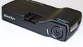
The EnGenius internet-connected camera. Courtesy of EnGenius.
The particular camera used in this teardown is the EnGenius EDS1130. This is a very low-cost camera, around $30 at the time of writing this. This camera offers Wi-Fi connectivity and 720p resolution.
Circuit Boards
There are two circuit boards inside of this camera. There is a primary PCB that controls nearly all of the functionality of the camera. There is also an IR circuit board that contains the IR lights and ambient light sensor.
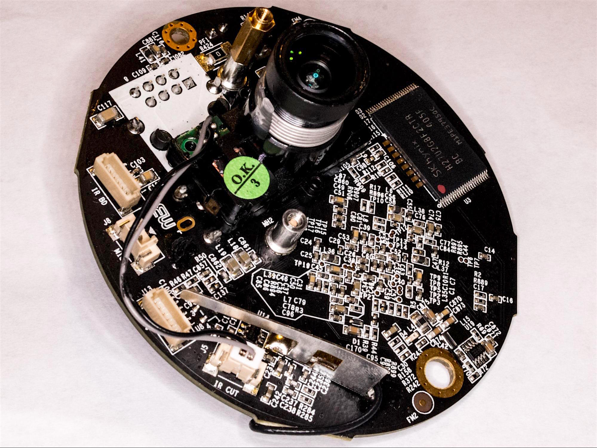
The top of the main PCB
The main circuit board is a unique board. It is an oval-shaped PCB with glossy black solder mask and white silkscreen on both sides. This PCB is mostly surface mount components, but there are a few through-hole components such as a relatively large electrolytic capacitor, ethernet jack, and power plug.

The bottom of the main PCB
The second circuit board inside of this IoT camera is the infrared board. This circuit board contains six IR LEDs and an ambient light sensor. Components are located on both sides of this circuit board with through-hole components located on the front and surface mount components on the rear. Connecting these two circuit boards is a pin cable.

The infrared PCB
System on a Chip

The Grain Media SOC used in this camera
Controlling nearly all of the functionality of this IoT camera is a Grain Media GM8126PF-BC SOC. This SOC contains a Faraday Technology FA626TE, ARM9 V5TE CPU, and H.264/MPEG-4 hardwired video encoders.
This SOC is intended for “Intelligent IP cameras” and “DVS” applications.

The Samsung RAM used in this camera
Connected to the Grain SOC is a 128 Mbit Samsung RAM IC, part number K4T1G164QG-BCE7, in a 60 FBGA package. This synchronous DDR2 memory achieves high-speed, double-data-rate transfer rates of up to 1066Mb/sec/pin.
Also connected to the Grain SOC is a 2Gbit SK Hynix flash memory IC, part number H27U2G8F2CTR-BC.

The SK Hynix 2Gb flash memory used in this camera
WiFi

The Mediatek MT7601U WiFi controller
In order to connect to WiFi networks this camera uses a MediaTek single-chip WiFi solution, part number MT7601U. The MT7601U supports IEEE 802.11b/g/n, in 2.4GHz only. A stamped metal Wi-Fi antenna is used to transmit and receive the data.
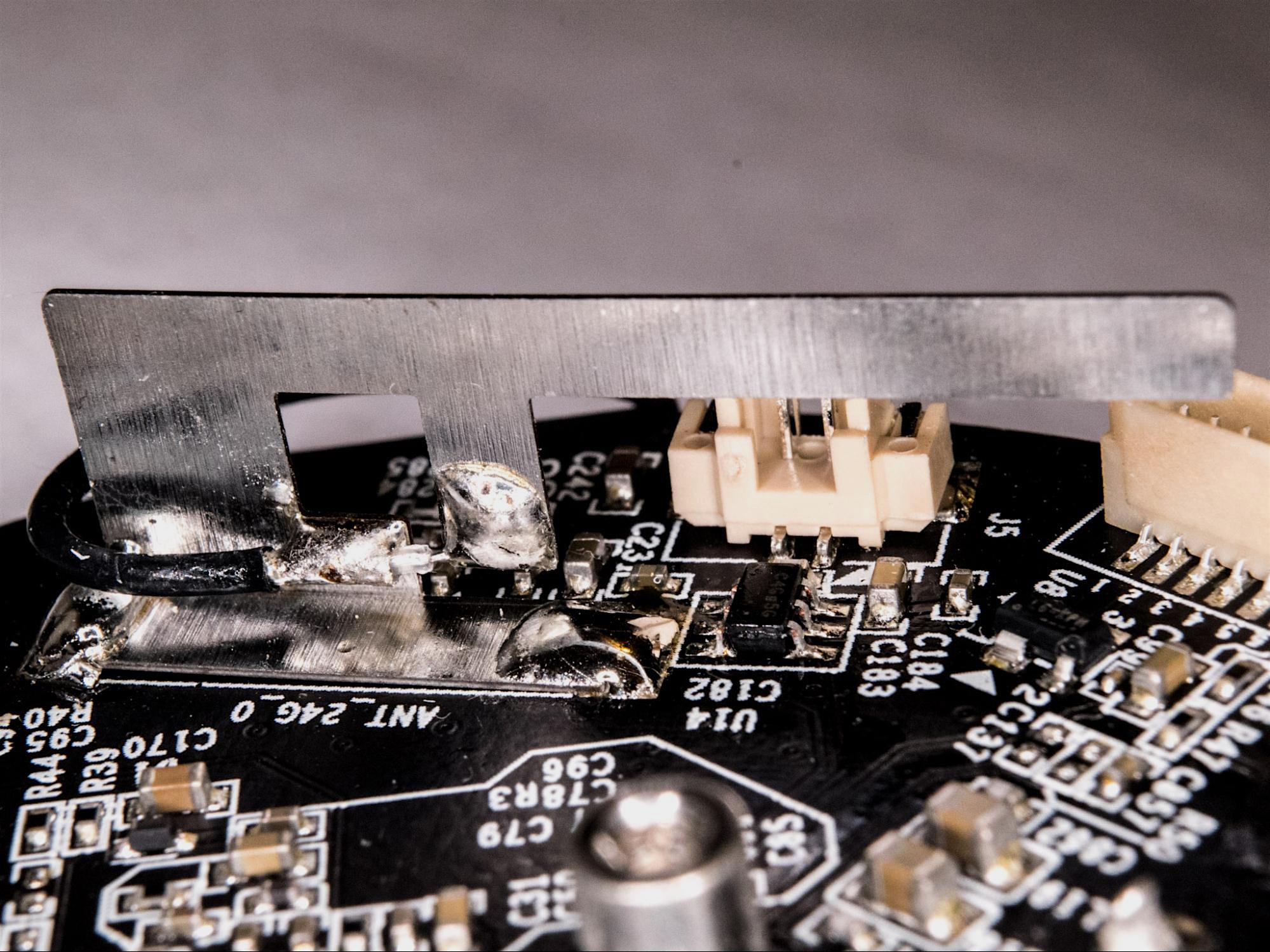
The 2.4GHz W-Fi antenna
Camera
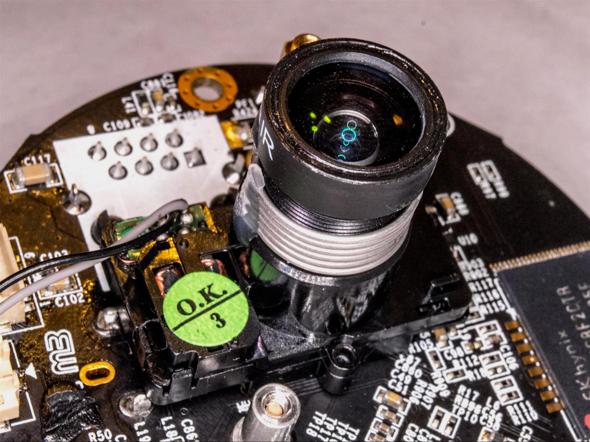
The camera module
No IoT camera would be complete without a camera! Located on the top of the main PCB is the camera. This camera consists of a lens assembly and IR filter assembly above a 720p board mounted camera sensor. The camera sensor is in a BGA package and lacks manufacturer markings.

The camera sensor
The lens assembly is mounted above the imaging sensor. The assembly has a lens that was focused at the factory, a rotary solenoid, a gearing mechanism, and movable filter.
This camera has the ability to see in the dark with the assistance of the IR LEDs. In order for the camera sensor to block IR light during the day, the lens assembly has two filters. The filter assembly slides right to left with the help of the rotary solenoid.
In the image below, the red-tinted filter can be seen over the aperture of the lens; this filter blocks out the IR light. To the left of the IR filter is a clear filter that lets the IR light reach the sensor, for use in the dark.

The IR filter mechanism
Wrapping it up!

A block diagram overview of the camera
The above block diagram shows a basic over of the inner workings of this IOT camera!
IoT devices are more popular than ever. With internet-connected electronics, like this camera, becoming cheaper and more widely every month, their sales probably aren’t going to slow down anytime soon!
Thanks for taking a look at this Teardown Tuesday!
Next Teardown: Credit Card Reader


Thank you for the chip references, very helpful!