Facebook
 Google
 GitHub
 Linkedin
Teardown Tuesday: Thermal Camera
In this Teardown Tuesday, we are going to take a look at the insides of an inexpensive thermal camera.
What's inside of a thermal camera? We'll find out in this Teardown Tuesday!
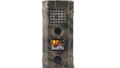
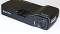
Thermal cameras have traditionally been very expensive, often costing thousands of dollars. Today there are a variety of options that are far more affordable, making them ideal for hobbyists and as a low-cost engineering tool. In this Teardown Tuesday we are going to take a look at the insides of one of these inexpensive thermal cameras. The particular camera we are tearing down is a Seek Reveal.

The Seek Reveal camera
Opening It Up

Thermal camera opened up
Last week I mentioned how easy the teardown of the Bluetooth Toothbrush was. This teardown, on the other hand, was more difficult.
On the back of the camera, there were six typical Torx screws. After these were removed, the back of the camera was easily taken off.
The difficult part of this teardown was removing the front of the camera. The front of the camera was attached with two specialty security screws. After a lot of searching, I foudn out that these screws are Penta-Plus manufactured by Bryce Fastener. These screws use a pin-in-pentagon (not to be confused with pentalobe screws).
The bits for these screws are sold from Bryce for around $20 with a $100 minimum order. These screws were removed by removing the center pin, using a similarly-sized Torx bit, and some friction. Below is one of the marred screw heads.

The marred penta-plus screw head
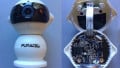
Circuit Board

The top of the camera's PCB
The circuit board inside of this camera is nothing out of the ordinary. The board has green solder mask and white silkscreen. The board contains surface mount parts on both sides of the PCB.
There are several active components on the top of the board and mostly passive components on the rear of the circuit board. Additionally, there are several unpopulated components, including a BGA, on the board.
Currently, there are several cameras made in this same form factor with varying levels of performance.

The rear of the camera's PCB
Microcontroller

The dual core NXP microcontroller
At the heart of this camera is an NXP microcontroller. The microcontroller used in this is an LPC4330FET180. This is a dual-core ARM M0/M4 microcontroller in a BGA package. Internally there is no ROM so an external program memory is needed. A 32 MBit Spansion (now Cypress) 5FL032P flash memory IC is used to store the program memory.

The 32Mbit Spansion flash memory
Battery and Charger

The li-ion battery in the camera
Powering the camera is a single cell lithium battery. This battery is made by EEMB, part number LP604765. Printed onto the cell is “1900mAh”, but according to EEMB’s website this part number has a nominal capacity of 1400mAh. This battery cell has a protection PCB attached to it.

The USB plug
In order to charge the battery, the camera uses a standard micro USB cable. The cable is also used for data transfers. To reinforce the connector, there is a fairly rigid glue used.
In order to safely charge the battery, there is a charger IC: a TI BQ24090. This charger features several safety features such as an input for an NTC and a 10-hour safety timer. Working with lithium batteries can be dangerous and safety mechanisms need to be in place.

The TI charger IC
Display

The top of the display
There is a 240px by 320px, 2.4”, LCD display that is used to show the thermal images. This display is mounted to the plastic internal frame and is connected to the circuit board through a ribbon cable. This display is manufactured by Tianma, part number TM024HDH71. A similar part, TM024HDH49, is listed on their website.

The rear of the display
Thermal Camera Module

The front of the thermal camera module
The thermal sensor of this camera is inside of a compact module. This module has a small germanium lens, an electromagnetic shutter controller, a circuit board, and a custom ribbon cable.
The ribbon cable has a ferrite bead around it to reduce interference. This is all encased in a metal housing with rubber shock mounts on all of its sides.

The rear of the thermal camera module
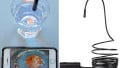
Flashlight Module

The flashlight LED and housing
Another feature of this thermal camera is the built-in 300-lumen flashlight. This light is mounted in the aluminum front of the of the camera. Around the flashlight cable is another ferrite bead. The light is controlled via a push button located on the side of the camera. The light's brightness is software-controllable.
Wrapping it up!
As you can see, there are quite a few components inside of this handheld device. Small thermal cameras like these are gaining popularity and are now sold by several manufacturers in various form factors. Do you need one for your workbench? Take a look at my article on how engineers can use thermal cameras to find out!
Thanks for taking a look at this Teardown Tuesday! Stop by next week for another teardown!
Next Teardown: Bluetooth Toothbrush