 Facebook
 Google
 GitHub
 Linkedin
Teardown Tuesday: Square Chip and NFC Reader
In this Teardown Tuesday, we are going to take a look at the insides of a Square chip reader.
In this Teardown Tuesday, we are going to take a look at the insides of a Square chip reader.
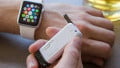
Square is a payment processing company that also makes hardware. Their first hardware was a small square white reader that plugged into the audio jack of a smartphone.

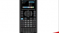
The Square chip and NFC reader
However, with the recent requirement in the United States to transition cards from magnetic stripe to EMV (chip) technologies, Square released a new device. This new device, referred to as the “Square Contactless and Chip Reader”, accepts NFC- and EMV-based payments.
Opening It Up

Prying off the bottom of the Square chip reader
To open the card reader, the bottom was first removed with a small screwdriver. The bottom was held on with an array of small plastic clips. An interesting observation is that the bottom lid has a small weight attached to it.
With the bottom removed, the PCB assembly was revealed. The PCB was held to the top of the plastic enclosure with two T9 Torx screws.
The last part of the teardown was removing the ‘security lid’. The security housing, intended to prevent tampering (more on this later!), was held in place with four Phillips head screws and two metal clips.

The PCBA inside of the plastic housing
The Circuit Board Assembly

The top of the PCB
With the circuit board assembly liberated from the plastic, I could have a look!
To start off with, it is a two-sided PCB populated entirely with surface-mount components. The blind vias indicate that this PCB has at least three layers. The board has an ENIG surface finish with black solder mask and white silkscreen on both sides.

The bottom of the PCB
Most of the SMD footprints are populated and the smallest passives appear to be resistors in a 0201 package. Also, attached to the circuit board assembly via adhesive is a lithium battery and a light pipe assembly.
Batteries

The 520mAh Li-Po battery
This Square reader has an internal rechargeable lithium battery that allows a wire-free operation. The pouch cell adheres to the PCB with very strong double-sided tape.
This battery is made by TCL Hyperpower Batteries, Inc., part number PR-244147A. It has a nominal voltage of 3.7V and a capacity of 520mAh for a total store energy of 1.92Wh. According to the battery's datasheet, it has a maximum charge rate of 1C (0.52A) and a maximum discharge rate of 2C (1.04A). The datasheet for this battery lists its lifespan as 300 cycles.

The two primary coin cell batteries
In addition to the rechargeable lithium battery, there are two primary coin cell batteries, size 364. These are part of the tamper-detection circuitry (again, more on that later!). These batteries are in series to produce around 3V. Primary lithium batteries of this size typically have around 15 to 20mAh. This pair of batteries is held in place with a pair of Keystone #3098 SMT coin cell holders.
Power Supply

The switching power supply
This device can be powered from the internal lithium polymer battery or through a USB cable. The board features a switching power supply, a TI LM2736 to step down the voltage to 3.3V. This is in a TSOT-23-6 with all of the required passives nearby.
Microcontrollers

The Freescale microcontroller
To control this chip reader is a Freescale K21 microcontroller. This is an ARM Cortex-M4-based microcontroller in a BGA package. This microcontroller has a built-in USB transceiver and a handful of other interface options.

The custom Square IC
In addition to the Freescale microcontroller, there is also a custom IC that is marked with the square logo. This IC handles the communication with the payment method, while the microcontroller handles the USB/Bluetooth interface.
It's also worth noting that the Bluetooth radio IC used in this device also has a programmable Cortex-M3 core and a Cortex-M0+ in it’s RF core. That is a total of three ARM cores in this one device.
Bluetooth Radio

The Bluetooth radio IC
To communicate, the Square reader relies on a Bluetooth connection. The TI CC2430 Bluetooth MCU takes care of the communication with the smartphone or tablet’s Square app.
Attached to the radio IC are two crystals and a handful of passives. A microstrip leaves the top left of the Bluetooth radio IC, goes through several passives for impedance matching, then makes its way along the top layer as it approaches the antenna and the tiny W.FL style jack.

A coaxial connector and antenna
Chip Reader and NFC Antenna

The NFC antenna
To read the information off of the cards (or NFC devices), this device relies on two methods. The first is an NFC antenna located on the top of the plastic housing. This antenna connects to the PCB via a three-position connector.

The card slot
There is also a ‘chip’ reader for chip-based cards. This mechanism is mounted to the PCB via surface-mount pins and some glue. This slot has tape on the top of it to prevent debris from entering the reader. This slot also has a built-in switch to detect the presence of a card.

Slot with the top off
Tamper-Proof Circuitry
When Square came out with their first hardware, they got a little bit of negative feedback due to its security (or lack thereof). This new device is a bit more secure. Opening the device reveals a security housing covering the card slot and several of the ICs.

The security housing
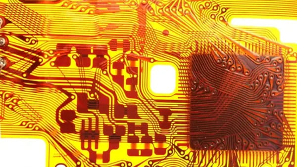
The security housing is made with a process called "Three-Dimensional Molded Interconnect Devices" or 3D-MIDs. This process uses an injection-molded part that has conductive traces applied to it using a laser-directed structuring process. If any of the conductors are broken or the housing is separated from the PCB, the encryption key is erased.

The 3D-MIDs conductors and contacts
The security housing makes contact with the PCB using four elastomer connectors. These touch the plated contact on the security housing and the exposed copper contacts on the PCB.
This chip reader uses two primary coin cell batteries to store the encryption information in volatile memory. These batteries supply power even if the primary rechargeable lithium polymer battery is depleted. In addition, the connections associated with this circuit are interconnected through blind vias, making it difficult to bypass or jumper around the tamper circuit.

One of the blind vias
Conclusion
For the price, (around $40USD at the time of purchase), there is a good bit of tech inside of this reader. My assumption on this is that Square isn’t making any money on this reader and instead relying on the ~3% it takes from card processing.
For more info on electronic payment systems, take a look at our teardown of a mag stripe credit card reader. Thanks for taking a look at this week's teardown, stop by next week for another!
Next Teardown: Mini Air Compressor


As the person who drew this board, thanks Alex!
FYI, there’s much more security in this unit than just in the plastic housing.