Facebook
 Google
 GitHub
 Linkedin
The Virtues of PWM Combined With a Power MOSFET
Pulse Width Modulation is a method commonly used to generate an analog signal output from digital input. But how is this feature enhanced when combined with a power MOSFET in a single device?
When STMicroelectronics recently released the VIPer Controller 730 V power MOSFET, one of the touted features was a built-in pulse width modulation controller. When suppliers advertise a device as having PWM capabilities, just how much can it affect your design? A closer look at the definition of PWM and certain use cases can tell us more.
What is Pulse Width Modulation (PWM)?
Pulse Width Modulation (PWM) is a method commonly used to generate an analog signal output from digital input. There are three factors to consider in this process:
- The amplitude of the digital signal
- Duty cycle
- Frequency, which determines how fast digital signal switches between zero (off) and 100% (on) of the amplitude
The duty cycle is defined as the length of the time the digital signal is on. In the figure below, the duty cycle is on 25% before going to zero.

Graph of duty cycle, measured by time and amplitude.
This cycle is said to have a 25% duty cycle, which can be adjusted. When the duty cycle is programmed on high (say, 90%) and the switching frequency is high enough, the output analog signal appears to be constant.
For example, a digital signal input of 10 V with a duty cycle of 40% will produce output analog signals of 10% × 40% or 4V. Likewise, a 6V digital signal with duty cycle of 30% will yield 1.8 V accordingly.
Why Use PWM?
A simple illustration will demonstrate the usefulness of PWM. Consider an AC light source of 110 V with a constant 110 V AC input. Using the PWM technique to generate the same output with 80% duty cycles will be more energy-efficient. If the switching is fast enough, the naked eyes will not be able to tell the difference. PWM can be applied to controlling motors and heaters as well.
ST's Power MOSFET-PWM Controller Hybrid
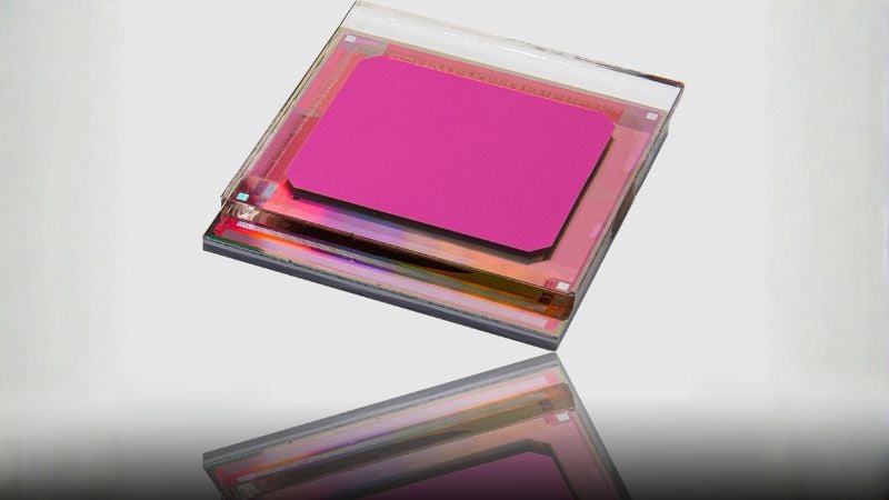
PWM now comes with the single power MOSFET silicon. One example we can use to illustrate the above principles is STMicroelectronics' VIPer controller 730 V power MOSFET with a built-in PWM controller.

ST's VIPer controller. Image used courtesy of STMicroelectronics
The device supports multiple power conversion topologies, including:
- Non-isolated flyback converters (AC-DC and DC-DC)
- Isolated flyback converters with primary-side regulation or secondary-side regulation using a photo-coupler
- Buck converters (DC-DC step down)
- Buck-boost converters (DC-DC using a single inductor instead of a transformer)
Some external components for the printed circuit assembly (PCA) layout are eliminated by the device’s embedded high-voltage startup and the current sense circuits, simplifying the bill of materials (BoM).

Block diagram of VIPer Controller 730 V power MOSFET. Image used courtesy of STMicroelectronics
Other functions include operating voltage (VCC) of 4.5 V–30 V, startup voltage of 30 V DC, high-voltage converters up to 8 W, and light-load power consumption of less than 40 mW (at 230 VAC). Additionally, it has the short-circuit, thermal, and pulse skipping protection.
Packaged in 5 mm x 4 mm SSOP10, the device operates from -40°C to 150°C with storage from -55°C to 150°C.
This device is geared for several applications, including home appliances, consumer, industrial (motors and heaters), lighting, building-automation devices, and smart meters.
Different Chips for Different PWM Needs
PWM is not new. Traditionally, PWM is achieved with discrete components or with a FET PWM controller. Many power silicon makers integrate new functions—including PWM—onto a single chip, including:
- LinkSwitch from Power Integrations
- MP172 from Monolithic Power Systems
- NCP1063 from ON Semiconductor
If your design requires external PWM, you might consider Maxim’s external FET PWM controllers (MAX17595 and MAX17598) for isolated AC-DC applications. STMicroelectronics’ low-pin-count VIPer controller is a useful choice if you're looking for multiple power conversion topologies with built-in PWM function.
Learn More About PWM
We just covered the basic dimensions of PWM in this article. To learn more, check out our other discussions on PWM.
Pulse-width Modulation (PWM) Timers in Microcontrollers
Low-Pass Filter a PWM Signal into an Analog Voltage
Modeling the Pulse-Width Modulator
From your experience, what are the benefits and tradeoffs of PWM? Share your thoughts in the comments below.