 Facebook
 Google
 GitHub
 Linkedin
Bootloading an AT328P-PU and Approximating the Functionality of an Arduino Uno…on the Cheap!
Reduce the cost of using an Arduino UNO by 50% or more by building your own device with comparable functionality.
A genuine Arduino UNO is a great development platform for a myriad of entertaining and useful microcontroller circuits, but including a complete UNO assembly in every project can be prohibitively expensive. With the instructions in this article, you can reduce that cost by 50% or more.
What is an Arduino? Are you sure?
It's hard to have lived on planet Earth since 2003 without learning something about Arduinos; love them or hate them, they are ubiquitous. But what is an Arduino, really?
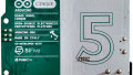
Contrary to what many people think, an Arduino is not a microcontroller; it is a particular brand of PCBAs (Printed Circuit Board Assemblies) that contain microcontrollers. The µC is most often an ATmega from the company Atmel (which is now a part of Microchip), and one of the most commonly used ATmegas is the AT328P. But not just any AT328P will function in an Arduino PCBA or with the Arduino IDE (Integrated Development Environment); the photo below shows what will happen when you try to upload a sketch to an ordinary AT328P that you purchased directly from a supplier.

As you can see, the upload failed ten times, and every failure was due to the same reason. Even though the error messages do not spell it out, the failures were because the ATmega microcontroller did not contain the Arduino bootloader, a small piece of code that tells the ATmega µC how to respond to the Arduino IDE instructions. Fortunately, the bootloader code can be uploaded to selected ATmega microcontrollers via a relatively easy process.
Step-by-step instructions for uploading the Arduino bootloader code to an AT328P-PU by using a genuine Arduino UNO follow. Essentially, the process breaks down into four parts:
- Building a bootloader circuit
- Setting the UNO up as an ISP (In-circuit Serial Programmer)
- Connecting the UNO to the bootloader circuit
- Uploading the bootloader code
After successfully uploading the bootloader code to the AT328P-PU, the bootloader circuit can be easily converted to a programming and operating circuit for the microcontroller, thus creating a development platform with many of the capabilities of a genuine UNO. This article will also provide details for that process.
Building the Bootloader Circuit
In order to upload the bootloader code from an Arduino UNO to a blank ATmega328P-PU, a small bootloader circuit is required. The parts needed for the bootloader circuit are listed below. (You'll also need some jumper wires.)
| Part Ref. | Description | Source | Item No. |
|---|---|---|---|
| R1 | Resistor, ¼ Watt, 10kΩ | Jameco | 691104 |
| C1, C2 | Capacitor, Ceramic, 22pF, 50V | Jameco | 81533 |
| C3 | Capacitor, Ceramic, 0.1µF, 50V | Jameco | 544921 |
| X1 | Crystal, 16MHz, HC49, 20pF | Jameco | 325139 |
| U1 | IC, ATmega328P-PU, 32KB Flash, DIP-28, 1.8-5.5V | Jameco | 2139111 |
| N/A | Breadboard, Solderless, 400 Contact | Jameco | 20601 |
| N/A | Arduino UNO R3 | Jameco* | 2151486 |
*Better yet, borrow an UNO from a friend just long enough to build your own.
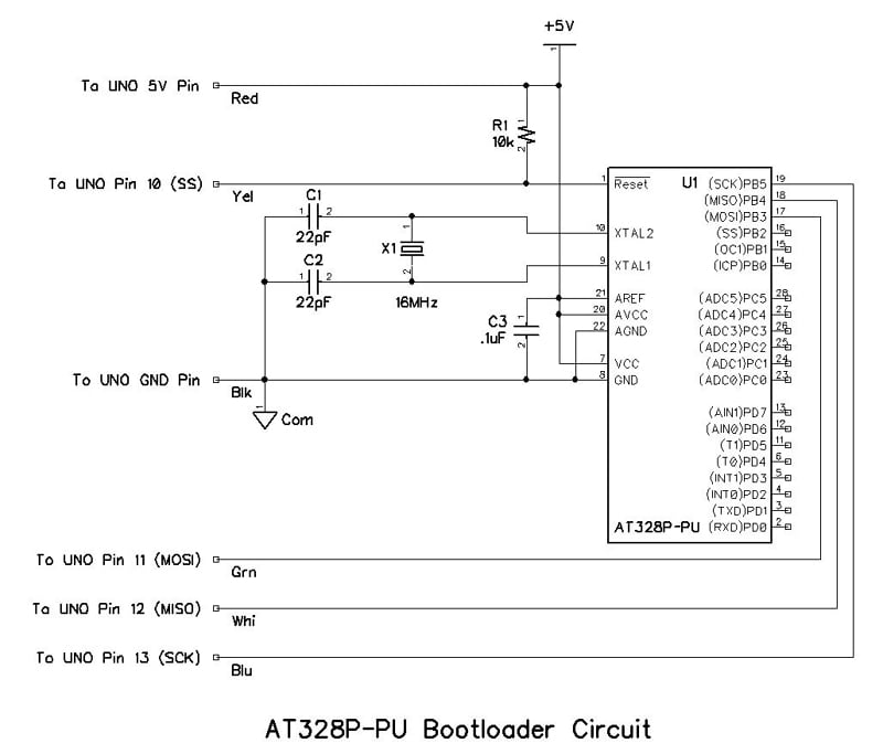
The schematic diagram for the AT328P-PU bootloader circuit is shown below and is very simple. The oscillator portion consists of X1, C1, and C2; note that X1 must be a 16MHz crystal and not 20MHz. Even though the AT328P-PU can use a 20MHz crystal, the bootloading process requires a 16MHz operation. R1 is a pull-up resistor for the Reset# pin, and C3 is a typical Vcc bypass capacitor.
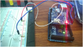
The callouts on the left of the schematic diagram define the pins on the UNO to which each lead should be connected, and the connections are displayed in the breadboard photograph following the schematic diagram. The wire colors called out in the schematic correspond to the wire colors in the photograph.
Note: assemble the bootloader circuit, but don't make the connections from the bootloader circuit to the UNO just yet.

Making the UNO into an ISP
After double-checking the wiring of the bootloader circuit, but before connecting it to the UNO, you must set the UNO up as an ISP (In-circuit Serial Programmer). Connect the UNO to your computer, start the Arduino IDE, and select the correct COM port for the UNO. Then, follow the steps as shown in the following screenshots from the Arduino IDE.
1. Identify the board connected as a genuine UNO.

2. Identify the UNO board's function as an Arduino ISP.

3. Open the Arduino ISP sketch.


4. Upload the Arduino ISP sketch to the UNO.

5. When you see the "done uploading" message, your UNO is ready to function as an ISP, and is capable of understanding and responding to instructions from the Arduino IDE.

Uploading the Bootloader Code
Now, connect the six leads from the bootloader circuit to the UNO exactly as shown in the schematic diagram and photograph provided above in the Building the Bootloader Circuit section. After double-checking all the wiring, you are ready to burn the following bootloader code into the AT328P-PU in the bootloader circuit.
1. Select "Burn Bootloader" as the function of the UNO; the process should start immediately when you click "Burn Bootloader."

2. When you see the "Done burning bootloader" message, the process is complete, and the AT328P-PU is capable of understanding and responding to instructions from the Arduino IDE.

Minimal Programming (and Operating) Circuit
The parts list for converting the bootloader circuit to a minimal programming and operating circuit is shown below.
| Part Ref. | Description | Source | Item No. |
|---|---|---|---|
| R2 | Resistor, ¼ Watt, 470Ω | Jameco | 690785 |
| C4 | Capacitor, Ceramic, 0.1µF, 50V | Jameco | 544921 |
| LED1 | Diode, Light Emitting, T1 3/4, Yellow | Jameco | 334108 |
| N/A | Converter, USB-to-TTL, with DTR Pin | on-line | N/A |
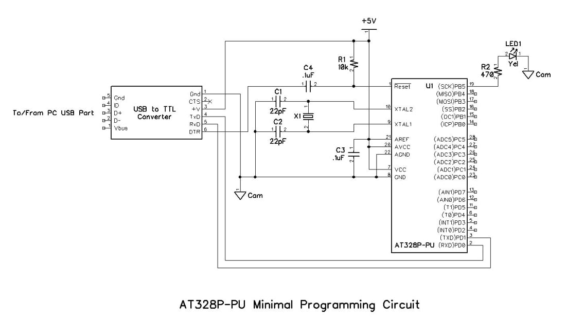
Converting the AT328P-PU bootloader circuit into a minimal programming and operating circuit as shown in the following schematic diagram and breadboard photograph is very easy.
- Remove all six wires that go between the UNO and the bootloader circuit.
- Connect R2 and LED1 between ground and pin 19 of the AT328P-PU.
- Connect pins 1, 3, 4, and 5 from the USB-to-TTL converter to the AT328P-PU, as shown. Pin 2 is not used.
- Connect pin 6 through C4, a 0.1µF capacitor, to pin 1 of the AT328P-PU. (C4 ensures that the DTR signal from the USB-to-TTL converter produces a transient reset signal, rather than one that remains at logic low for an extended period of time.)

Uploading the First Sketch: Blink, of Course
1.In order to confirm operation of the AT328P-PU minimal programming and operating breadboard, open the "Blink" sketch from the basic examples included with the Arduino IDE.

2. After selecting the correct COM port, compile and upload the "Blink" sketch to the AT328P-PU.

The first attempt to upload the "Blink" sketch failed; can you see why it failed? Hint: look at the bottom right corner of the IDE window above, and compare it to the same area of the two IDE windows below (in which the upload was successful.)


Of course, the reason the first upload attempt failed was because the wrong COM port (3) was selected instead of the correct COM port (6).
What Happened?
Success! You have uploaded the Arduino bootloader into an AT328P-PU and then uploaded the "Blink" sketch to the AT328P-PU, as confirmed by the blinking yellow LED on the minimal programming and operating circuit breadboard. Now, any other functional Arduino sketch may likewise be uploaded, and the components required for that sketch may be attached to the AT328P-PU, and used successfully.
Have Arduino fun . . . and do it for less money!
Give this project a try for yourself! Get the BOM.
Related Content


Hey Charles, Thank you very much for such a great and informative explanation, I’ve faced this problem before some days, and I had to buy burner circuit for it.
I am curious about Atmega8, what if I replace Atmega8 with Atmega328, can I burn bootload to Atmega8 ??
dear Sir! i m still facing problem while uploading bootloader showing the message
“avrdude: Yikes! Invalid device signature.
Double check connections and try again, or use -F to override
this check.
Error while burning bootloader. ” what to do with this problem???
Your picture of the AT328P-PU minimal programming and operating breadboard is nice. I would like to know which pins map to the Arduino Digital 0-13 and Analog 0-7 once the Arduino bootloader is in place.