 Facebook
 Google
 GitHub
 Linkedin
Breadboard and Program an ESP-01 Circuit with the Arduino IDE
The ESP8266 combination microcontroller/Wi-Fi modules can now be programmed using the Arduino IDE. Here's how!
ESP8266 Microcontroller/Wi-Fi Integrated Circuit
A new microcontroller has captured the attention of professional designers and hobbyists alike, and it has the potential to be a force majeur in the internet of things. Bearing the nondescriptive name "ESP8266", this highly integrated circuit consists of a 32-bit RISC processor with all the bells and whistles you would expect in a full-featured µC, but that's not all. The ESP8266 also includes a built-in 802.11 b/g/n Wi-Fi circuit that is ready to be directly connected to an antenna.
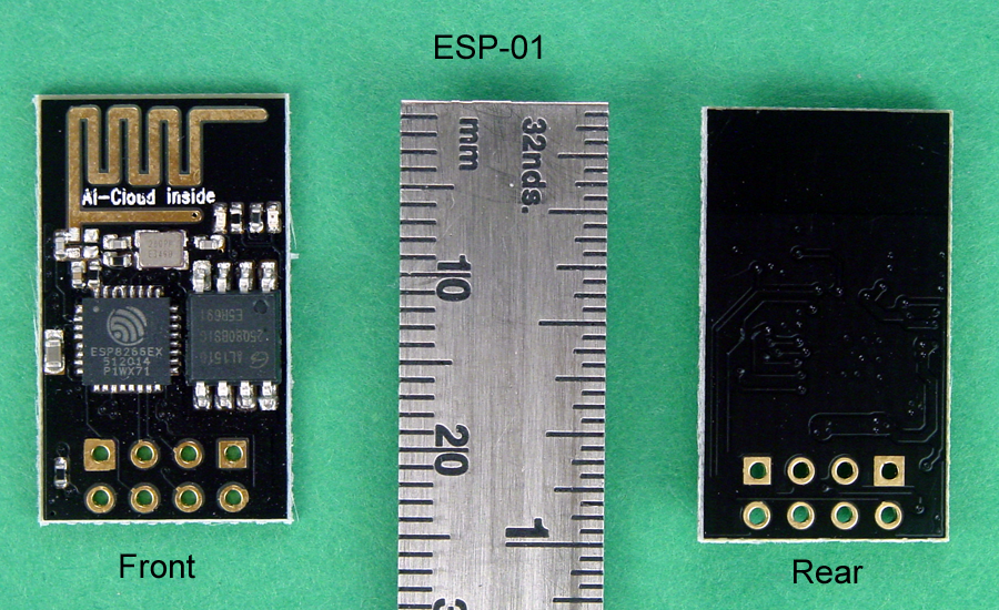
The ESP8266 is currently available only in a 32-pin QFN package, and there is just one IC in the family. The developer, Espressif, in Shanghai, China, has chosen to take full advantage of manufacturing efficiencies of scale and offer a single IC that is suitable for use on a variety of PCB assemblies. Presently, there are more than a dozen ESP PCB modules that differ primarily in antenna styles and the number of I/Os available. Because of the ESP8266's QFN package, most hobbyists will be pleased with that decision, especially since market prices start at less than US$5 for the low-end model, dubbed the ESP-01, and pictured below. Click the photo for a larger image.
A very active community support forum exists for the ESP8266, and is an excellent source for ideas and information. Originally, documentation was only available in Chinese, and firm application information can still be hard to come by. Currently, many DIY projects are operating in the "trial and error" mode, but there are many aftermarket suppliers who are selling development platforms and accessories. However, as you will see later in this article, it's not difficult to get an ESP8266 up and running on a solderless breadboard.
Programming Options
From the supplier, many (maybe all) of the ESP8266 modules are loaded with "AT" firmware, and can be programmed via a simple terminal program. If you are using the module primarily to exploit its Wi-Fi capabilities and controlling it with another µC, this could be all you need.
A more sophisticated option is available from NodeLua, which offers open source firmware based on the Lua programming language. NodeLua is still in development, but already contains extensive capabilities. Other choices include Python, BASIC, and the Arduino IDE, which is featured in this article.
ESP-01 Ins and Outs
The ESP-01 module contains the ESP8266 MCU and a flash memory chip. There are two LED's: a red one which indicates power is connected to the module, and a blue one which indicates data flow, and can also be controlled by user programming. The Wi-Fi antenna is the PCB trace that covers the top of the module; it's called a Meandered Inverted-F Antenna (MIFA,) is surprisingly efficient, and only mildly directional.

There are eight connection pads near the bottom of the module; the figure above identifies their functions. Usually, two 4-pin male headers are inserted in the rear of the module and soldered on the front. This makes the I/Os accessible, but is not breadboard friendly, and requires flywires from the ESP-01 to a solderless breadboard. This technique works, but it is messy. There is an alternative way as shown below.
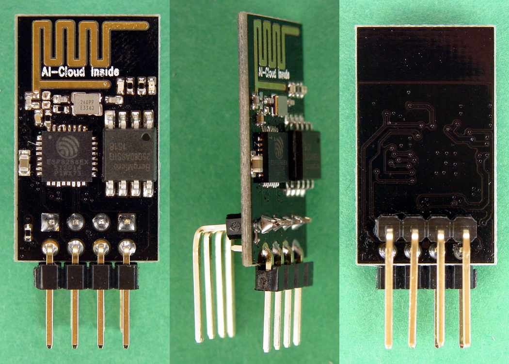
The header on the front of the PCB uses standard right angle pins with no modifications required. The header on the rear uses extra long pins that have been bent in a right angle configuration to accomplish .3" of separation between the rows. This method allows the ESP-01 to be inserted in a solderless breadboard in the vertical orientation straddling the center gap, and makes all eight pins independently accessible.
Connecting Things Together
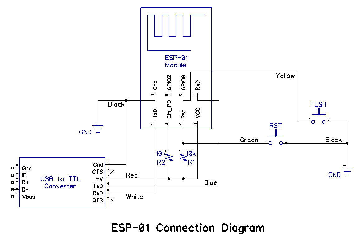
The schematic diagram below shows the connections required to the ESP-01, and the photographs show the completed solderless breadboard assembly. The wire colors on the schematic correspond to the wire colors in the photographs.
Construct the assembly as shown, but do not connect the cable from the USB to TTL converter to the PC until you have set the shunt on the converter PCB to the 3.3V position, and double checked all wiring. Using 5V to power the ESP-01 could damage it beyond repair.
Editor's note: A more reliable flashing circuit is available here, and should be used instead of the circuit described in this article.
.png)
.png)
.png)
Between the schematic diagram and the photographs, you should have most of the information needed to assemble the solderless breadboard setup. The notes below will also help.
- The USB to TTL converter shown in the photographs utilizes an FTDI 232 UART chip and works well with Windows, Mac, and Linux operating systems. It also provides a 3.3VDC power source for the ESP-01. Be certain that the shunt on the converter PCB is set to output 3.3V; that will ensure that both the supply voltage and the TxD signal will be at the correct voltage. Using a higher voltage could damage the ESP-01.
- Whatever USB to TTL converter you decide on should be installed and tested prior to using it with the ESP-01 breadboard setup. Drivers for FTDI devices are located at the FTDI web site.
- Estimates of the current required for the ESP-01 during Wi-Fi operation vary from 250mA to 750mA. The current supplied by the USB to TTL converter should suffice for programming the ESP-01, but may prove to be inadequate for long term use. A better choice is a filtered regulated 3.3VDC supply capable of 1A or more.
- The DTR and CTS leads from the USB to TTL converter are not required and are not connected.
- The two switches shown are normally open (NO) single pole momentary contact pushbuttons.
- One of the discrepancies in the information available for the ESP-01 is whether CH_PD should be connected directly to +3.3V, or should be connected through a 10k pull-up resistor. The author has tested both methods, and has found both to work. After you build and test the circuit as shown here (with CH_PD tied directly to +3.3V,) try using a 10k resistor instead of the direct connection. If the circuit works with the 10k pull-up resistor, leave it in the circuit.
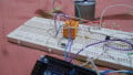
As you see in the photographs above, the use of fly wires from the USB to TTL converter is not optimum. A better option is to replace the six right angle pins on the converter with six straight pins on the bottom of the PCB. The modification will allow the USB to TTL converter to be plugged into the solderless breadboard and will result in a much neater and less fragile assembly, as shown in the following photo.
.png)
Powering Up
Before connecting the USB to TTL converter to your PC, check to be sure that the voltage selection shunt is in the 3.3V position, and that all the wiring on the ESP-01 breadboard setup is correct and secure. Then, plug the USB cable in; the red LED on the ESP-01 should light and stay on, and the blue LED should flicker whenever there is signalling between the EXP-01 and the PC. Next, test the reset switch by pressing and and holding it down. Look at the ESP-01; when you release the reset switch, the blue LED should flash twice. If all is well at this point, disconnect the circuit from the PC and proceed to the next section.
Arduino IDE
The recommended Arduino IDE version for use with the ESP8266 modules is Version 1.6.5. If you have an earlier version, you can try it and see if it works, or you can upgrade to 1.6.5.
- Once the proper Arduino IDE is installed, start the program and click File, Preferences, and look for the entry box for Additional Board Manager URLs. Enter the following URL exactly as it is written and then click OK.
- http://arduino.esp8266.com/stable/package_esp8266com_index.json
- Next, click Tools, Board Manager, and scroll down the list to find "esp8266 by ESP8266 Community." Select this entry and click the Install button; downloading and installation will begin and continue for a few minutes. While it is installing, take a look at the different platforms supported. In addition to the generic ESP8266 Module, support is provided for the NodeMCU, the Huzzah, and the SweetPea. By the time you read this, probably more will have been added.
- When the installation is finished, click the Close button.
- Now, click Tools, highlight the Board selector, and choose "Generic ESP8266 Module."
- Click Tools again, and visually confirm that the board selected is Generic ESP8266 Module.
- Click File, Examples, and scroll down the list until you come to ESP8266WiFi, and then click WiFiScan. A new IDE window should open containing the WiFiScan sketch.
Reconnect the circuit to the PC and confirm that the red LED on the ESP-01 is lit. Click Tools, Port, and select the port where the ESP-01 is connected. Finally, you are ready to program the ESP-01.
Press and hold the Reset button, and then press and hold the Flash button. Release the Reset button, and while holding the Flash button pressed, click the Upload arrow in the Arduino IDE. The sketch should compile in a minute or so, and when it is complete, release the Flash button. The compiled code will be sent to the ESP-01; as it is sent, the blue LED on ESP-01 will flicker.
To see the results of all this clicking and choosing, click Tools, Serial Monitor, and set the baud rate in the lower right corner of the Serial Monitor window to 115200. If you have an earlier version of the ESP-01 (probably built on a blue PCB,) the baud rate is most likely 9600.
The ESP-01 should be scanning for Wi-Fi networks and reporting the results in the Serial Monitor window, as shown in the example below.

You should see your own network in the report, and all other networks that are within range of the ESP-01. The numbers in parentheses show each network's signal strength, and because the numbers are negative, lower numbers represent stronger signals.
The Door is Open
The ability to program an ESP8266 using the Arduino IDE hugely expands the user base for these Wi-Fi enabled chips. The ESP-01 and its larger cousins provide an extremely capable hardware platform at a low cost. Add the ease of use of the Arduino IDE, and designing applications for the internet of things is within the reach of almost anyone.
What will you connect to the web?
Give this project a try for yourself! Get the BOM.


I hope your ready to fix peoples problem the AT commands was removed from the SDK because of some licensing problem. And there are just as many or more with LUA on them the ESP8266-1 came with AT on it. Thats almost 2 years old now. The ESP8266-12 all have LUA on them. I have six of the ESP8266-12 and the model with a Q on the end there all LUA and all are from AI they now have a free AT for the ESP again the one they used at first was something with a MIT license and was open source. And the arduino Ide if you program a esp with it flashes it lot’s of people don’t understand that and end up not being able to do stuff they did before using the arduino ide to program the esp stand along.
Built exactly as shown but get an error at the end of the flash procedure.
“error: espcomm_open failed”
Know it works from a terminal POV as I can sent and receive AT commands in Coolterm.
hi iam getting warning like this
WARNING: Category ‘’ in library EEPROM is not valid. Setting to ‘Uncategorized’
WARNING: Category ‘’ in library ESP8266httpUpdate is not valid. Setting to ‘Uncategorized’
WARNING: Category ‘’ in library Hash is not valid. Setting to ‘Uncategorized’
WARNING: Category ‘’ in library SPI is not valid. Setting to ‘Uncategorized’
WARNING: Category ‘’ in library Ticker is not valid. Setting to ‘Uncategorized’
WARNING: Category ‘’ in library Wire is not valid. Setting to ‘Uncategorized’
Warning: platform.txt from core ‘ESP8266 Modules’ contains deprecated recipe.ar.pattern=”{compiler.path}{compiler.ar.cmd}” {compiler.ar.flags} {compiler.ar.extra_flags} “{build.path}/{archive_file}” “{object_file}”, automatically converted to recipe.ar.pattern=”{compiler.path}{compiler.ar.cmd}” {compiler.ar.flags} {compiler.ar.extra_flags} “{archive_file_path}” “{object_file}”. Consider upgrading this core.
after compiling the wifi scan program