 Facebook
 Google
 GitHub
 Linkedin
Build a Laser Communication System
Use a laser and a photo resistor to build a laser based point-to-point communication system. The best part? It's under $10.
Who doesn't love lasers? Let's do something more than make a dot on the wall with a laser: let's build a communication system for less than $10.
Safety First: Even before starting this project I want to mention to always be careful with lasers: even a weak laser can cause permanent damage to the human eye in a few seconds. More powerful lasers may cause blindness instantly. Never shine a laser at anybody's face, animals included. If working with a powerful laser, I strongly recommend making a laser lab, and using laser goggles for the frequency of your laser. With that covered, let's move on to what you came here for: a fun, safe project using LASERS!
A communication system pretty much always breaks down to two parts, a transmitter and a receiver. Laser communication systems are no different: the laser is the transmitter and for the receiver we will use a photo-resistor. So really it's two circuits. For this project I am going to keep both of them very basic. This means this project could be completed in just one evening, and it's inexpensive. So let's start with the parts list.
Parts Needed
Components needed for one channel
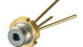
- laser diode
- GM5539 photoresistor
- 2 LF347 op-amp
- 1 transistor
- 12 resistors
- 3 capacitors
- 2 9 volt batteries
And for lab equipment
- multimeter
- function generator (optional)
- oscilloscope (optional)
For high quality lasers, Thor Labs has some good options but the cheapest one I saw was $12. Mouser has a decent looking laser in the visible spectrum for $11.45. Or for cheap lasers for home projects amazon or ebay are a good choice, with options under $1 per laser. The GM55XX series photo-resistors have a rise time of 20ms, and the fall time of 30ms. If you buy the GL55XX series photoresisters, expect poor frequency response that makes them unsuitable for anything much above audio frequencies, and noticeable signal loss for high frequency audio. The long rise and fall time make the GM55XX series a poor choice for any square wave applications. For high frequency receivers, I recommend using a photodiode.
Specifications
For my design, I want to send audio from my tablet to a set of computer speakers. This means my input is max 2Vpp from 10Hz to 22KHz. I would like my output to also be 2Vpp from 10Hz to 22KHz, but will suffer losses at higher freqencies. Sound quality should be better than AM radio. The transmitter and reciver should each be powered by their own 9V battery.
Transmitter Design
Because I'm sending a continuous analog signal, I will need my laser bias such that the laser is on at all times. If you are sending a digital signal I still recommend this, as some lasers do not like to be pulsed at high frequencies. I am going to bias my laser at 4.5VDC and modulate it from 4V to 5V. First measure the current draw of the laser at 5V, for my laser it was drawing 29mA. This is more than what many op-amps can provide so I will power my laser with a transistor set up as a voltage follower. To drive the voltage follower, I will use a op-amp to mix my input signal with 4.5V and attenuate the signal from 2Vpp to 1Vpp.
![]()
![]()
To test the transmitter, I used my function generator as an input and measured the voltage across the output with my oscilloscope. If you don't have an oscilloscope, use your multimeter to measure the voltage across the laser and just vary the input from -0.5V to 0.5V. Once the laser is modulating correctly, it's time to set up and align your laser.
Alignment
Here's how I aligned my laser for a desktop set up. However you do it, you need to align the laser and photoresistor so that you can get accurate measurements of your photoresistor with the laser incident on it.
I started by drilling a hole the same size as my laser in a block of wood. Then I fixed the laser in the block of wood (mine is just held in through pressure but glue could be used). The block of wood with my laser was then glued to a long piece of 1.7cm X 3.5cm wood. I powered on the laser and placed a second block of wood on the other side, marked where the block of wood was located and the location of the laser dot on the block of wood, giving me a separation of 40.4 cm. I then drilled a hole for the photoresistor and glued it in, being careful to keep the legs of the photoresistor separate.
Glue the second block of wood where you marked it. Turn the laser back on and you should have your laser dot on the photoresistor. This is not practical for a large setup, but for just setting it up on the desk it works well.

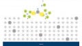
This is my setup. I added some paper shields because the laser dot was so bright. On the right you can see the leads for the laser, and on the left you can see the leads of the photoresistor poking through the paper.
Receiver Design
To start, we will want to get measurements of the resistance of the photoresistor. I started by just reading the values in some arbitrary locations.
| No light | >2 Meg ohm(my DMM read open circuit) |
| Full Sun | 675 ohm |
| Room light | 36k ohm |
I then set up the laser and my photoresistor in my alignment setup. I then took some more measurements. Because these will vary with the distance, laser aperture, laser wavelength, laser power, and other conditions, I strongly recommend generating your own results.
| Laser Voltage (Volts) | Resistance (ohm) |
| 0(room light) | 172k |
| 4.0 | 911 |
| 4.1 | 842 |
| 4.2 | 817 |
| 4.3 | 775 |
| 4.4 | 748 |
| 4.5 | 718 |
| 4.6 | 709 |
| 4.7 | 692 |
| 4.8 | 657 |
| 4.9 | 648 |
| 5.0 | 633 |
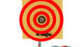
Graphing the values helps to see that it's not perfectly linear, but reasonably close over this small range of values.

To design the receiver, I'm going to make a voltage divider using the photoresistor. I will then connect that to the input of an inverting amplifier. The inverting amplifier output is then passed into a highpass RC filter with a cut off of 10 Hz, this will remove the DC component without any major effects on the audio quality of the system. To select the second resistor for my voltage divider, I looked at my measurements of the photoresistor and choose the value that was closest to the 4.5v measurement. That gave me a values for R7 of 680 ohms, I could then use that to solve for was would likely be my max and min voltages. That gave me a voltage that would voltage ranging from 3.84V to 4.37V, a swing of 0.82V. For the gain stage, I would need a gain of 2.4 to regain my original 2V input. Because of the poor rise and fall time of the photoresistor, I gave myself some extra gain and built a stage with a gain of 3.6, then began testing and quickly decided to up the gain further to 5.4, a much higher gain than expected.
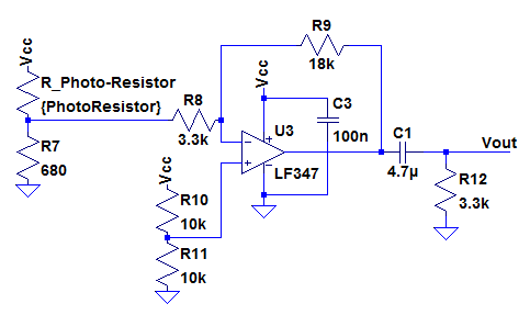

Any design of a variable gain could be used as the receiver: you could use a transistor gain stage an op-amp, or some other method of detection.
Now to test the system. I used my function generator to provide a sine wave as the input, and then measured the output of the receiver. As expected strong frequency dependence was found, with -3dB corners of about 20Hz and 550Hz.

Now that we have measured the performance of the system, a real test of the sound quality was in order. I connected my tablet to the input, and the output to a set of computer speakers.
Playing "Son of Man" from Disney's Tarzan and then breaking the laser beam to show that it is working. Sound quality is not perfect, and you can hear the loss of the higher frequencies. As for the specs, the pass band is not close to 22kHz, but the output has reasonable sound quality, similar to AM radio. You won't be hosting any parties with this system, but you could easily have a private conversation over the system.
So that's how you can build a very basic laser-based communication system for under $10. If you want 2-way communication, build a second copy of the system so that each side has both a receiver and transmitter. If you build a system with multiple channels going in each direction, you may want to use linear polarizers to prevent "cross talk" and allow you to pack more receivers in a small space.
Give this project a try for yourself! Get the BOM.
Related Content


Back in the ‘40s, when I was in high school, I built a flashlight communications system. It consisted of an amplifier, low power; a flashlight, that I modulated with the amp, and a rectifier plate from a car battery charger as the receiver feeding into another amp. This was very crude, but it worked. These days it is really nice to have all the items readily available to make a sophisticated system.
What are the applications of this project
Could mount this on “Frikkin Sharks With Frikkin Lasers”