 Facebook
 Google
 GitHub
 Linkedin
How to Build a Particulate Matter Detector for Air Quality Measurement
Use a Honeywell particle sensor to measure 2.5 µm PM and 10.0 µm PM concentrations in your environment.
This project uses a Honeywell HPM series particle sensor to measure and display 2.5 µm PM and 10.0 µm PM concentrations of particulate matter in the air of your environment.
Particulate matter (PM) is defined as the combination of solid particles and liquid droplets found in the air. Some particles are large enough to be seen with the naked eye while others are microscopic. Very small particles are of particular importance as these can be readily inhaled. When inhaled concentrations are large enough and exposure is long enough, they are linked to adverse health effects.
Particle size can be characterized in micrometers (abbreviated µm) or microns; both terms are a unit of length defined as one millionth of a meter (10-6). Since we are interested in evaluating the amount of particulate matter in the air, it is useful to represent the quantity as a concentration; that is, micrograms of PM per cubic meter of air (µg/m3).

Comparison of various particle sizes (figure courtesy of the USEPA).
For air quality, particle sizes are frequently grouped into two categories: those smaller than 2.5 µm and those smaller than 10.0 µm. In this regard, the USEPA sets standards for exposure to such “particle pollution”. The standards are expressed as a function of particle concentration and exposure duration (e.g., 24 hour and annual).
PM in our environment comes from many different sources, including man-made and natural processes. Outdoor particle pollution is monitored and is part of the Air Quality Index (AQI) that is available for areas in the US.
In this project, we will use a Honeywell HPM series particle sensor to measure and display PM concentrations in sampled air. PM monitoring has a variety of industrial and consumer applications including general air quality measurement as well as specific relevance to processes associated with heating, ventilation, air conditioning, air filters and air purifiers.
The HPMA115S0-XXX Particle Sensor

The HPMA115S0-XXX particle sensor: Left, front of unit containing the air inlet; Right, back of unit showing the exhaust fan and the interface connector.
The sensor is an integrated unit that contains a laser light source, detection chamber, photodiode, exhaust fan and a communications interface. Particles are counted using the light scattering method.

Functional diagram of the sensor’s operation (figure courtesy of Honeywell PDF).
An internal laser light source illuminates particles as they are transported, via the air inlet and the exhaust fan, through the detection chamber. Particles obscure the light and change the electrical activity of an internal photodiode. That activity is analyzed and converted to a particle concentration, which can be transmitted through the serial interface.
Sensor Interface and Commands
The HPMA115S0-XXX communicates with a host using a UART at 9600 Baud, 8 data bits, no parity and 1 stop bit (9600, 8, N, 1). The device accepts the seven commands as listed below and detailed in the device datasheet PDF.
Command Function
- Stop Particle Measurement: Turns off the internal exhaust fan.
- Start Particle Measurement: Turns on the internal exhaust fan.
- Read Particle Measurement: Returns 2.5 µm PM and 10.0 µm PM concentrations (µg/m3).
- Enable Auto Send: Automatically sends a 32-byte packet that contains the 2.5 µm PM and 10.0 µm PM concentrations (~ 1/second).
- Stop Auto Send: Turns off Auto Send.
- Set Customer Coefficient: The customer coefficient can be used to modify the slope of the calibration curve (values above 100 increases the slope, and values below 100 decreases the slope). Consultation with Honeywell is recommended if you want to use this function.
- Read Customer Coefficient: Returns the current Customer Coefficient value.
Based upon my evaluation, the following default conditions are used on power up, regardless of any subsequent changes; the internal fan is turned on, Auto Send is enabled, the Customer Coefficient value is 100. Changes made after power-up are volatile and are not saved internally (i.e., the default values will be restored at the next power-up).
As shown in the datasheet, command sequences are sent with a checksum formed using the formula (65536-(datum1+datum2+datumN)) modulo 256. In addition to the checksum, commands will also return a positive or negative acknowledgment sequence (Pos ACK or Neg ACK, respectively).
Using the Particle Sensor with a PC
Project BOM: HPMA115S0-XXX Particle Sensor, USB-to-serial board (see text), connectors (see text).
To gain access to the HPM interface, I used an 8-position, 1.25 mm pitch, mating connector and pre-crimped single-ended leads. Other connection methods are possible, including making your own leads and I admit that I chose the easy way.
I used the USB-to-serial board illustrated below (available here and from other sources).

USB-to-serial interface board for use with a PC.
A word of caution, however; there are many such USB-to-serial boards available and it is essential that you choose one that operates at 3.3V to match the sensor’s serial interface. It is advisable to actually check the lines with a voltage meter as feeding a 5V signal into the sensor’s UART exceeds the limits specified in the datasheet. The board that I chose has a 5V-3.3V switch that, when in the 3.3V position, actually transmits 3.3V signals on the TXD line while preserving a 5V line to power the sensor (which requires a maximum of 80 mA). Not all USB-to-serial boards will have these characteristics.
Alternatively, if you only have 5V signals on the USB-to-serial board, you can use a voltage level converter (example here). In this regard, it is notable that a regulated 3.3V out line is available on the sensor’s connector.
The schematic below illustrates the connections between the USB-to-serial board and the HPM particle sensor - note again that the RX, TX, RXD and TXD signals are all at 3.3V.

Connections for the HPM sensor to the USB-to-serial board.
Using an HPM Terminal Program
The project program, HPM Term, is written in Visual Basic using Microsoft Visual Studio Community 2017 Version 15.5.2. The version of Visual Studio is available as a free download. The program files, both integral files that you can use to build the program yourself and a deployment package, are available for download at the end of the article.
Using the program is relatively straightforward. After connecting the HPM to the USB serial port board, simply plug the board into a USB port on the PC (see important note below).
Run the program and select the appropriate COM port and click the “Connect” button. At this point, you can use the command buttons on the left side of the screen to execute any of the commands that the sensor allows. The terminal will display, in hexadecimal, both the sequence of bytes sent to the sensor and the bytes received from the sensor for each action.
Important Note: Upon connection, a stream of 32-byte packets are sent from the sensor about once per second. This occurs because the unit powers up with Auto Send enabled as previously mentioned. Most unfortunately, however, I found that on my PC (Windows 7, 64 bit), the OS would decide (apparently misinterpreting the byte stream) that a Microsoft Serial Ballpoint Mouse had been connected and proceed to load a driver for that device, which caused a lot of problems as you can imagine.
After a good deal of research and frustration, I found that this behavior is known to occur with several devices and, most notably, GPS devices (see these links for more information, 1, 2, 3).
The easy solution that I used was to simply disconnect the RXD line into the USB-to-serial board (i.e., the TX line from the HPM) until establishing the connection in HPM Term. Thereafter, the RXD line can be reconnected with no further problems. I don’t know if this problem occurs in other OS versions and you can read about other proposed solutions in the aforementioned links.
The screen capture shown below illustrates use of the program.

Screen capture from HPM Term.
In this example, both the Serial Out and Serial In windows were first cleared and then the Read PM button was clicked. The command bytes (in hexadecimal) sent to the sensor were 0x68, 0x01, 0x04 and 0x93. Those values constitute the Header (0x68), the command length (0x01), the command (0x04) and the checksum (0x93). The checksum is calculated by taking the lowest 8 bits of the result of subtracting the sum of the bytes from 0x10000. That is, ((0x10000-(0x68+0x01+0x04)) AND 0xFF) = 0x93. Sometimes, this is referred to as a “256-modulus checksum” and is based on the algorithms know as Fletcher’s checksum.
The Serial In window contains the response sent by the sensor (again, in hexadecimal) as 0x40, 0x05, 0x04, 0x00, 0x09, 0x00, 0x0A, 0xA4. Those values constitute the header (0x40), the response length (0x05) and the command (0x04) and serve as a positive ACK (acknowledgement). The bytes that follow tell you the 2.5 µm PM concentration in high byte, low byte order ((0x00 * 256) +0x09), the 10.0 µm PM concentration, again in high byte, low byte order ((0x00 * 256)+0x0A) and finally, the checksum value (0xA4).
In the case of a negative ACK, indicating that the sensor could not respond with the PM values, the response sequence would be only 0x96, 0x96. In my experience, however, I have not observed this to happen.
The datasheet for the sensor gives detailed examples of all the command interactions. That information can aid exploring the sensor functions with HP Term.
Constructing a Stand-Alone PM Detector
Project BOM: HPMA115S0-XXX Particle Sensor, Teensy-LC controller, OLED 128 x 32 display (see text), 4.7K resistors (2), connectors (see previous text).
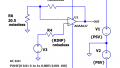
While connecting the HPM sensor to a PC was worthwhile for exploration of the device, I also wanted to make a stand-alone PM detector. The schematic below shows the circuit that I used.

Schematic for the stand-alone PM detector.
For the controller, I used a Teensy-LC. The board, illustrated below, features an ARM Cortex-M0+ processor at 48 MHz, 62K Flash, 8K RAM, 12 bit analog input & output, hardware Serial, SPI & I2C, USB, and a total of 27 I/O pins (technical specifications here).

Teensy-LC microcontroller.
The board can be programmed using an AVR C compiler, but it can also be used with the well-known Arduino IDE with the Teensyduino addon. Moreover, many Arduino libraries will also work with the Teensy-LC.
The HPM sensor requires a 5V supply for power. On an unmodified Teensy-LC board, 5V is available on a pin that comes directly from the USB socket as long as you use a standard 5V USB power source, such as a USB wall wart or a portable battery with 5V out on a USB connector like the one pictured below:

Image courtesy of Microcenter.
It is notable that if you cut a trace on the board to provide a different input voltage source for the board (i.e., separating Vin from VUSB), then you will not be able to use the pin in the same fashion.
I used a hardware serial port on the board (RX1 and TX1) to communicate with the HPM sensor’s serial port (RX and TX). Since both the Teensy-LC and HPM sensor serial ports are 3.3V, they are compatible with each other.
Having the ability to read the PM values from the sensor established, I needed to add the capability to see those values. The detector is designed to simply be powered up and continually provide the detected PM concentrations. Thus, a simple display seemed appropriate.
I settled on a small OLED display as illustrated below.

128 X 32 OLED display.
These tiny (~0.91 inch, 128 x 32) OLEDs use an SSD1306 controller, contain an I2C interface and are available from many different sources (see an example here).
The OLED is powered from the 3.3V out pin on the Teensy-LC, and I used the I2C interface (SCL0 and SDA0) with the supported and familiar Arduino Wire library. Additionally, 4.7K pull-up resistors are used on each I2C line. The 4.7K value is recommended for the Teensy-LC and works without any problems.
I also used the U8g2 monochrome graphics library, which supports the SSD1306 controller and makes it very easy to write to the display.

The complete stand-alone PM detector on a breadboard.
Source Code for the Stand-Alone PM Detector
The entire program for the Stand-Alone PM Detector, Honeywell_HPM.ino, appears below and is included in the project download. The code is straightforward and is commented, but a few notes are in order.
Basically, the program simply runs through a loop that reads and displays the PM concentrations every six seconds. The variable, delaymsecs, can be altered to adjust the read and display rate.
In the setup portion, we make multiple attempts to disable the Auto-Send feature of the sensor as it is enabled on power up. During this time, you will see ‘9999’ on the display and if an ‘E’ persists on the display, it means that Auto-Send could not be turned off and likely indicates a connection/communication problem.
The routines for reading the sensor will also make multiple attempts at a successful read before displaying an ‘e’ next to the displayed values to notify the user of a communications issue. The ‘e’ will be removed, however, upon a successful read.
Both routines use a maxattempts variable to determine the number of times that the communication is tried before displaying an error notification. The variable is set equal to 2 by default. This is done to alert the user to potential communication issues. Except when intentionally forcing errors, I never observed such communication errors in normal testing.
When the PM concentration exceeds the values for the variables, WPM25 or WPM100, an asterisk is displayed next to the respective concentrations. The default program values are 35 (µg/m3) and 150 (µg/m3), for PM 2.5 µm and PM 10.0 µm, respectively. The values were chosen on the basis of EPA standards for 24-hour exposure.
The threshold values, however, can be set by the user or disabled by entering 9999, since the upper range of the sensor does not exceed 1000 µg/m3.
Finally, an easy way to test the detector is to blow out a lit match near the air inlet. The PM values should increase substantially.
//-------------------------------------------------------------------------------------------
// Honeywell_HPM.ino
// Code to accompany the article:
// "Build a Particulate Matter Detector for Air Quality Measurement"
//
// Program to run the PM 2.5u/10.0u Particulate Matter Air Quality Sensor
//
//*** This software Is offered stricly as-is with no warranties whatsoever.
//                     Use it at your own risk.  ***
//-------------------------------------------------------------------------------------------
// Programmed for the Teensy-LC
// Uses a 128 X 32 OLED, SSD1306 controller
// Arduino IDE 1.8.5 and Teensyduino 1.41
// Uses the U8g2 Library for monochrome displays, version 2.20.13

#include
#include

// function prototypes
void conPM(int PMvalue, char *charArray);
bool StopAuto(void);
bool ReadPM(void);

#define HWSERIAL Serial1 // Rx on 0 and Tx on 1 for LC

// oled definition
U8G2_SSD1306_128X32_UNIVISION_F_HW_I2C u8g2(U8G2_R0);

// prefixes for each line
//const char s25[] = {' ', '2', '.', '5', 181, '=', 0};
//const char s100[] = {'1', '0', '.', '0', 181, '=', 0};
const char s25[] = {' ', '2', '.', '5', 181, 'm', '=', 0};
const char s100[] = {'1', '0', '.', '0', 181, 'm', '=', 0};
// storage of particle values as char array (after conversion)
// we will display at [1] since max value is 1000 as per datasheet
char v25[] = {'6', '5', '5', '3', '5', 0};
char v10[] = {'6', '5', '5', '3', '5', 0};

// calculated particle measurement values
unsigned int PM25, PM100;

// warning vaues (set to 9999 for no warning)
// these defaults are based on EPA values for 24 hours
unsigned int WPM25 = 35;
unsigned int WPM100 = 150;

int delaymsecs = 6000; // delay for read (min is <6000 from data sheet)
                       // testing indicates 2 seconds will work

//--------------------------------------------------------------


void setup(void) {
  // Note: Upon power up, the HPM defaults to Fan and Auto Send On
  u8g2.begin();
  HWSERIAL.begin(9600, SERIAL_8N1);
  // display template on OLED
  u8g2.clearBuffer();           // clear OLED memory
  u8g2.setFont(u8g2_font_10x20_me);
  u8g2.drawStr(0, 14, s25);
  u8g2.drawStr(70, 14, "9999");
  u8g2.drawStr(0, 31, s100);
  u8g2.drawStr(70, 31, "9999");
  u8g2.sendBuffer();            // transfer internal memory to the display
  delay(1000);
  // stop HPM default auto send
  while (StopAuto() == false) {
    // display error
    u8g2.drawStr(118, 14, "E"); // display warning
    u8g2.sendBuffer();
    u8g2.drawStr(118, 31, "E"); // display warning
    u8g2.sendBuffer();
  }
  // clear error on recovery
  u8g2.drawStr(118, 14, " "); // clear warning
  u8g2.sendBuffer();
  u8g2.drawStr(118, 31, " "); // clear warning
  u8g2.sendBuffer();
  delay(5000);                // initial settle
}

void loop(void) {

  if (ReadPM() == false) {
    // display read error ('e')
    u8g2.drawStr(118, 14, "e"); // display warning
    u8g2.sendBuffer();
    u8g2.drawStr(118, 31, "e"); // display warning
    u8g2.sendBuffer();
    // note: 'e' will be cleared on a succesful read below
  }
  else {
    // display PM values on the OLED
    // note: we only display 1000s down as
    // per max value from data sheet
    conPM(PM25, v25);
    u8g2.drawStr(70, 14, &v25[1]);
    u8g2.sendBuffer();
    conPM(PM100, v10);
    u8g2.drawStr(70, 31, &v10[1]);
    u8g2.sendBuffer();
    if (PM25 > WPM25) {
      u8g2.drawStr(118, 14, "*"); // display warning
      u8g2.sendBuffer();
    }
    else {
      u8g2.drawStr(118, 14, " "); // clear warning
      u8g2.sendBuffer();
    }
    if (PM100 > WPM100) {
      u8g2.drawStr(118, 31, "*"); // display warning
      u8g2.sendBuffer();
    }
    else {
      u8g2.drawStr(118, 31, " "); // clear warning
      u8g2.sendBuffer();
    }
  }
  // wait 6 seconds (default) before sending the next request
  delay(delaymsecs);
}

void conPM(int PMvalue, char *charArray) {
  // convert the particle measures to char array storage for display
  //  with leading zeros. Note: no error checking!
  byte digit = 0;
  bool LZ = true;

  for (int div = 10000, mod = 0; div > 0; div /= 10) {
    mod = PMvalue % div;
    PMvalue /= div;
    if (!LZ || PMvalue != 0) {
      LZ = false;
      charArray[digit++] = PMvalue + '0';
    }
    else {
      charArray[digit++] = '0';
    }
    PMvalue = mod;
  }
  charArray[digit] = 0; // zero delimiter
}

bool StopAuto(void) {
  // attempt to stop the default power up auto send
  // if it fails, an 'E' will be displayed on the screen
  // in a terminal loop until a successful transmission
  // Note: this should never happen an indicates a
  //      chronic serial transmission error.
  byte maxattempts = 2; // set this as you like
  byte attempts;
  int R1 = 0, R2 = 0;

  // wait until there is a pause in Auto-Send
  while (HWSERIAL.available()>0)
  {
    HWSERIAL.read();
  }
  attempts = 0;
  bool result = false;
  while (attempts < maxattempts) {
    HWSERIAL.clear();
    // send a stop auto send
    HWSERIAL.write(0x68);
    HWSERIAL.write(0x01);
    HWSERIAL.write(0x20);
    HWSERIAL.write(0x77);
    // read response
    delay(25);
    // if there are no bytes ready, -1 is returned
    R1 = HWSERIAL.read();
    R2 = HWSERIAL.read();
    if ( (R1 != 0xA5) || (R2 != 0xA5) ) {
      attempts++;
    }
    else {
      attempts = maxattempts;  // force an exit
      result = true;          // with an ok return
    }
  }
  return (result);
}

bool ReadPM(void) {
  // send a read request and get the particle measures in the response
  // if we don't get the bytes back or we have a checksum error
  // return false - else return true

  byte maxattempts = 2;   // set this as you like
  byte attempts = 0;      // attempt counter
  byte R[8];              // response bytes
  int nbytes;             // byte counter
  unsigned long ck;       // for checksum calculation
  bool result = false;

  while (attempts < maxattempts) {
    // send a read request send
    HWSERIAL.clear();
    HWSERIAL.write(0x68);
    HWSERIAL.write(0x01);
    HWSERIAL.write(0x04);
    HWSERIAL.write(0x93); //cksum
    delay(25);
    // we want to read 8 bytes of data
    // Pos ACK - 0x40,0x05,0x04
    // DF1,DF2 - 2.5 high / low
    // DF1,DF2 - 10.0 high / low
    // Cksum (mod 256)
    nbytes = 0;
    ck = 0;
    while (HWSERIAL.available() && nbytes < 8) {
      R[nbytes++] = HWSERIAL.read(); // store the byte
    }
    if (nbytes == 8) {
      // we got them and R[7] hold the checksum
      ck = ((65536 - (R[0] + R[1] + R[2] + R[3] + R[4] + R[5] + R[6])) & 255);
      if (ck == R[7]) {
        // everything looks good so calculate the global particle measures
        PM25 = (R[3] * 256) + R[4];
        PM100 = (R[5] * 256) + R[6];
        attempts = maxattempts;
        result = true;
      }
      else {
        //checksum error
        attempts++;
      }
    }
    else {
      // serial tx error [not enough bytes]
      attempts++;
    }
  }
  return (result);
}
Program files for the project can be downloaded by clicking the link below.
Here's a short video of the system in action:
Closing Thoughts
In this project, we interfaced a HPMA115S0-XXX Particle Sensor to a PC using a serial interface and we also constructed a stand-alone detector to monitor 2.5 µm PM and 10.0 µm PM concentrations. In general, I am impressed by the sophistication of the sensor and the relative ease of its use.
In my view, this sensor has some interesting applications for evaluating indoor air quality in the home and workplace and can also be useful to evaluate the efficiency of air filtration systems.


Interesting reading thanks for the thorough background information.
Operation of this Honeywell device is similar (but not the same) to the Nova SDS011 and SDS012, for which I recently wrote an Arduino library.at https://github.com/gitpeut/SDS021. As the Honeywell device is not significantly more expensive, I will have a look at it in the future.
Thanks!
Thanks for the article.
I’m testing the Honeywell device, but I get different values depending on the sample rate (the delaymsecs variable).
If i set delaymsecs = 2000, I get PM25 = 4 and PM100 = 5, but If I set delaymsecs = 10000, I get PM25 = 0 and PM100 = 1, if I set delaymsecs = 100 (I know that is a low value) I get PM25=200 and PM100=390
The same behaviour happens if i use the library https://github.com/felixgalindo/HPMA115S0
Do you know what is the reason? is my sensor damaged?
Thanks!