Facebook
 Google
 GitHub
 Linkedin
How to Build a Tachometer/Speedometer with an Optoelectronic Sensor, a Microcontroller, and a Disc
Learn how to make a tachometer and speedometer using a C8051 microcontroller, an optoelectronic sensor, and a spinning disc.
Learn how to make a tachometer and speedometer using a C8051 microcontroller, an optoelectronic sensor, and a spinning disc.
This project uses a C8051 microcontroller development kit, an optoelectronic sensor, a variable-speed DC motor, a 5-inch diameter transparent disc, and the Simplicity Studio IDE to quickly and easily build a tachometer and speedometer. The measured data is sent to a terminal window via the UART.
This is part one of a two-part project. Part two will display the data on an LCD screen using a keypad to cycle through the measured data. You can jump ahead to learn how to add a keypad and LCD.
C8051F930/ Microcontroller Development Kit
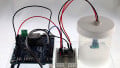
The C8051F930 development kit is intended as a development platform for the microcontrollers in the C8051F92x-C8051F93x MCU family. This kit comes with the C8051F930 microcontroller installed—see Figure 1 below.
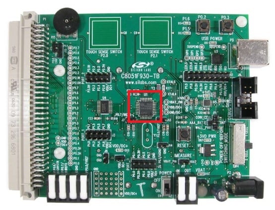
Figure 1. C8051F930 development kit. C8051F930 microcontroller (red box).
The C8051F930 microcontroller includes the following features:
- Single supply: 0.9 to 3.6V
- High-speed 8051 µC core
- 10-bit ADC
- 4352 bytes internal data RAM
- 64kB Flash memory
- 24 port I/O
- SMBus, I2C, 2× SPI, UART
- On-chip debug
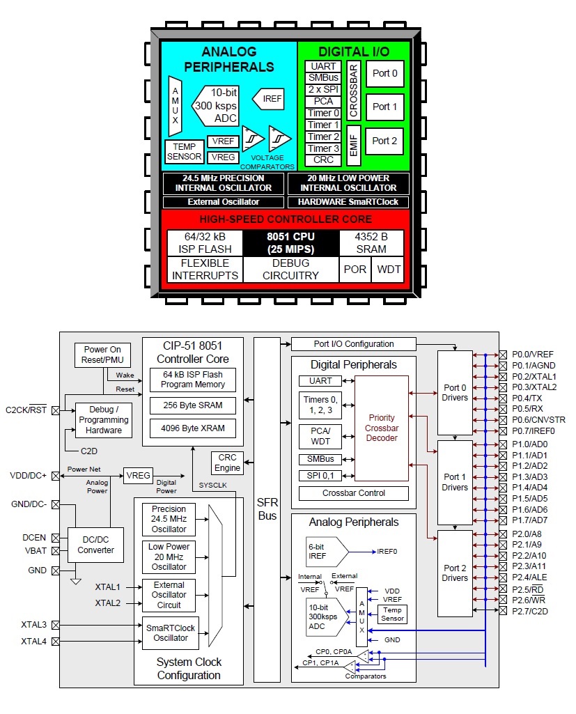
Figure 2. C8051F930 block diagrams. Image from the datasheet via Silicon Labs
The Silicon Labs IDE, called Simplicity Studio, can be downloaded here.
Optoelectronic Sensor
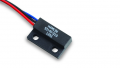
The optoelectronic sensor used for this project is technically called, by its manufacturer, a slotted optical switch. The manufacturer part number of this optical switch is OPB816Z. I chose this particular device because of its rather large gap/slot opening—0.20" (5.1mm) wide and 0.61" (15.5mm) deep—which allows the spinning disc to "float" in the slot. I knew that I needed some space for floating to occur because I would be using my wobbly hand to hold the motor and spinning disc during initial testing.
This optical switch uses an infrared-emitting diode and an NPN phototransistor. The switching of the phototransistor occurs whenever an opaque object passes through the slot: When no barrier exists between the diode and the phototransistor, the phototransistor is conducting and the output is low (~0.2V). In contrast, when a barrier blocks the diode's IR illumination, the phototransistor is in cutoff and the collector node is pulled high (3.3V).
Another reason for deciding to use this device is that, as can be seen in the figure below, it's pre-wired using 26AWG wires (24" in length). This pre-wired option makes the wiring of this device to my breadboard much easier.
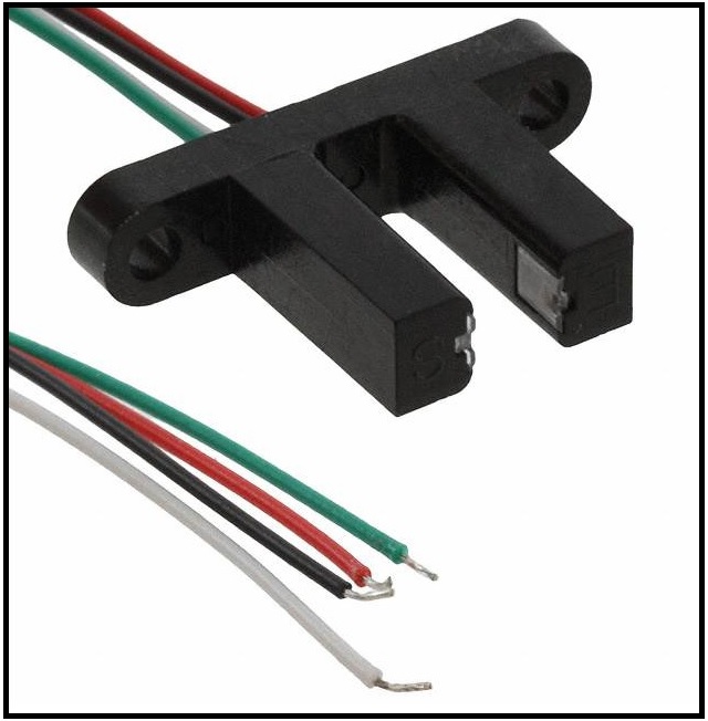
Figure 3. Pre-wired optical switch (slot-type). Image courtesy of Digi-Key
DC Motor
For this project, I re-purposed a DC motor that I found/removed during a printer teardown. The motor is characterized as a carbon-brush motor that is rated to operate at up to 42VDC. During my testing as well as in my demonstration video below, I powered the motor using a variable DC voltage ranging from 0V to about 12V.
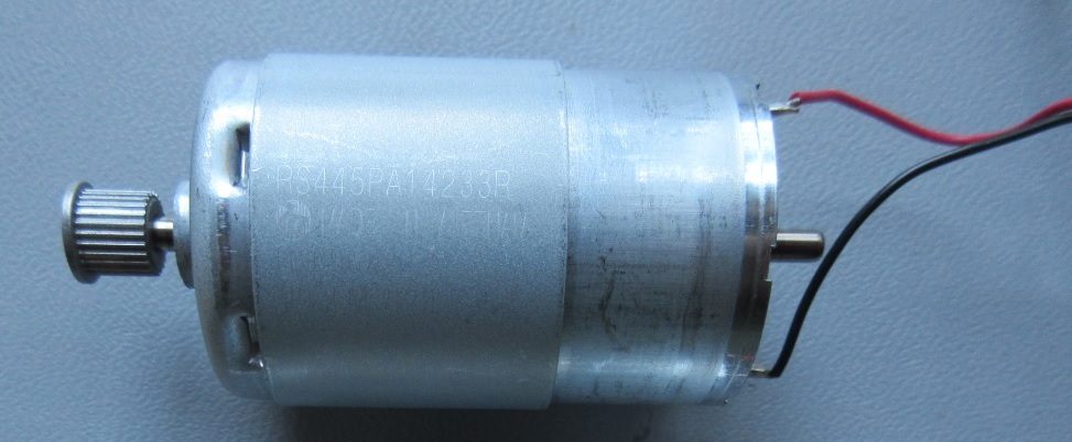
Figure 4. DC motor
Spinning Disc
For the disc, I wanted something that was quite rigid yet fairly thin, no greater than 6 inches in diameter (for ease of use), and transparent. I decided on a 5-inch-diameter, 1/16-inch-thick, clear acrylic plexiglass disc from Source One LLC. The figure below shows the disc—the blue covering is merely a protective film.
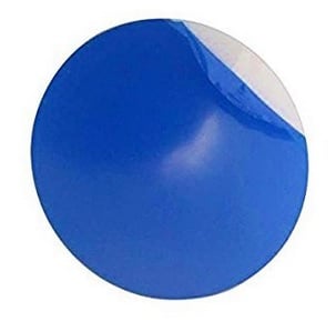
Figure 5. Five-inch diameter clear disc.
Parts List
| Item # | Description / Source | Cost (each) | Other Information |
|---|---|---|---|
| 1 | C8051F930 Development Kit | $99.00 | User Guide Quick-Start Guide C8051F930 datasheet Note: schematics are on pages 23-25 of the User Guide. |
| 2 | Breadboard | $8.98 | or equivalent |
| 3 | Jumper wire kit | $5.28 | or equivalent |
| 4 | Clear Acrylic Plexiglass Disc | $7.99 | |
| 5 | Optical Sensor | $3.62 | |
| 6 | DC Motor | $6.55 | The motor used in the project was re-purposed from a printer teardown. However, this motor looks to be an equivalent motor. |
| 7 | Resistor: 3.3k-ohms | $0.10 | or equivalent |
| 8 | Resistor: 75-ohms | $0.10 | or equivalent |
Attaching the Disc to the Motor
One challenge that I encountered (granted, it's a minor challenge) was determining how to securely attach the motor to the disc. Remember, this disc will be spinning relatively fast: I'm expecting at or above 30 rev/s (revolutions per second).
If you look a little closer at Figure 4 above, you'll notice a gear that is installed on the motor's shaft. And because I couldn't remove the gear, short of cutting it off—trust me, I tried real hard—and because I'd like to re-purpose the disc and motor in the future, my aim was to mount the disc in a manner that wouldn't permanently alter either the disc or the motor. As it turns out, the protective film attached to the disc is actually very secure and doesn't move around at all. Therefore, I tried, successfully and proudly, to epoxy the motor's gear to the protective film/attached paper label (see Figure 6).
At the conclusion of this project, I anticipate being able to remove the epoxy from both the motor, using one of many solvents in my garage, and the disc, by simply removing the protective film from the disc itself. This will allow me to reuse both parts in another project.
Finally, after the epoxy cured, I trimmed back some of the protective film and placed a thin strip of tape (~2mm in width) on the disc (see Figure 6). This tape serves as the barrier between the IR-emitting diode and the phototransistor, and thus it functions as the triggering mechanism of the optical switch for measuring the revolutions per second of the disc as it spins.
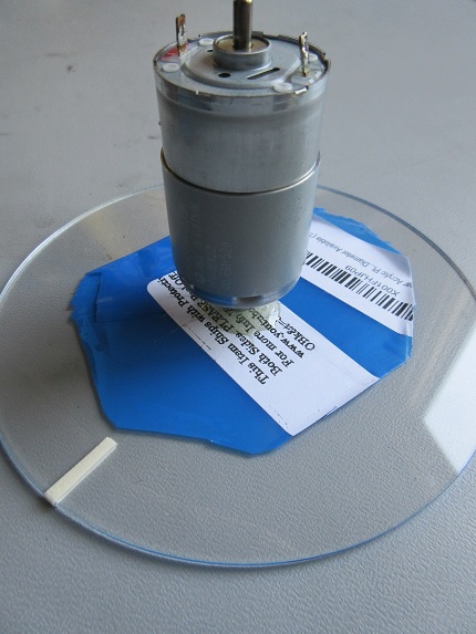
Figure 6. Motor epoxied to disc.
Making the Connections / Schematics
The microcontroller's port 1 pin 2 (P1.2) is configured as a digital input and is connected to the collector of the phototransistor.
Choosing R1's Value
R1 must be sized such that the phototransistor will enter saturation when there is no optical barrier.
The sensor's datasheet says that the minimum on-state collector current is 1 mA and that the maximum VCE in saturation is 0.4 V. Thus, the resistor must drop at least (3.3V - 0.4V) to ensure saturation: 2.9V / 0.001A = 2900Ω, so resistance greater than ~3kΩ is adequate.
Choosing R2's Value
The calculation above assumes that the diode forward current is 20mA, so we should size our resistor for IF = 20mA. The only forward voltage spec that we have is 1.8V at IF = 20 mA:
$$R_2=\frac{(3.3V-1.8V)} {20mA}=75\Omega$$
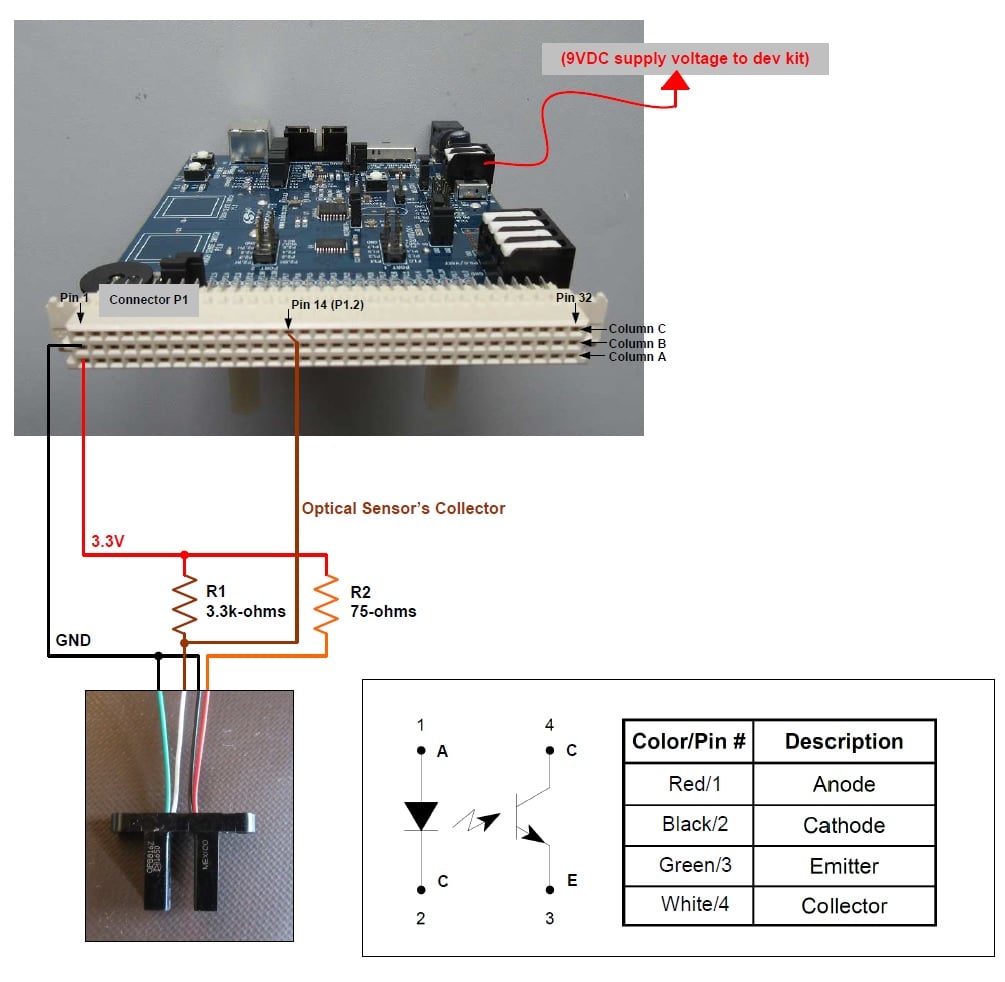
Figure 7. Connection diagram. Click to enlarge
Configuring the Microcontroller Development Kit
Before powering up the microcontroller development kit, be sure to configure it as follows:
Jumpers:
- J11: VBAT to WALL_PWR
- J12:
- VDD to VIO
- P0.5 to TXD
- J17: VBAT_PIN to VBAT
Switches:
- SW4: set to "2 CELL"
- Power switch (SW5) to "OFF" position—we'll change this later on.
Cables:
- Connect the ribbon cable debug adapter to J9
- Connect the USB debug adapter to your PC.
- Connect the USB serial-port cable between P3 and your PC.
- Connect the supplied AC/DC power adapter to P2.
Calculations for Firmware
As mentioned previously, when the slot of the optical switch has no barrier the phototransistor will conduct, and with a properly sized resistor the phototransistor will be in saturation. This means that the collector voltage will be about 0.2 V, i.e., logic low. When the phototransistor is prevented from "seeing" the IR-emitting diode, it is in cutoff and the collector node is pulled high by R1. The firmware will count the number of times, per given amount of time, that a barrier is present between the phototransistor and the IR-emitting diode. Using this data we will first calculate the angular velocity (ɷ) in units of revolutions per second, and then, using the angular velocity, we will calculate the disc's linear speed (in both feet per sec and miles per hour) at its radius using the following equations.
$$c=circumference\ of\ a\ circle = 2*\pi*r\ (inches)$$
$$distance\ traveled\ as\ the\ circle\ (disc)\ rotates= 2*\pi*r\ (inches/revolution)$$
$$linear\ speed = \omega\ (revolutions/s)\ *\ c\ (inches/revolution)$$
$$linear\ speed = \omega*c\ (inches/sec)$$
To convert to feet per sec (ft/s):
$$linear\ speed = \omega \frac{1}{(sec)}* c\ (inches) * \frac{1\ (feet)}{12\ (inches)}$$
$$linear\ speed = \frac{\omega * c} {12}\ (feet/sec)$$
To convert to miles per hour (MPH):
$$linear\ speed = \omega \frac{1}{(sec)}* c\ (feet) * \frac{1\ (mile)} {5280\ (feet)} * \frac{3600\ (sec)}{1\ (hour)}$$
where,
$$\omega = angular\ velocity\ (rev/sec)$$
$$r = radius\ of\ disc = 2.5\ (inches)$$
$$c = circumference\ of\ disc = 2* \pi *r = 2* \pi*2.5\ (inches) = 15.708\ (inches)$$
The angular speed will be displayed in both rev/s and rev/min (RPM).
The linear speed will be displayed in both feet per second (ft/s) and miles per hour (MPH).
//-----------------------------------------------------------------------------
// StartTimer Routine
// ----------------------------------------------------------------------------

		if(StartTimer == 1)
		{
			TimerPeriod = 0;			// Reset
			TimerT2 = HUNDRED_MICROSECOND_TIMER;    // Set TimerT2 to equal HUNDRED_MICROSECOND_TIMER value.
			TimerPeriod = (TimerT2-TimerT1);	// Take the difference between the beginning and the end of the timing cycle.
			TimerT2 = 0;				// Reset
			HUNDRED_MICROSECOND_TIMER = 0;		// Reset
			StartTimer = 0;				// Clear this flag.
			AverageAccumulator += TimerPeriod;	// Add the current timer period measurement to the accumulator.
			AverageMeasurements--;			// Decrement the measurement counter.

			if(AverageMeasurements == 0)
			{
				TimerPeriodAverage = (AverageAccumulator / 100.0);			// Calculate the average value: divide the summed AverageAccumulator by the number of measurements.
				FrequencyAverage = ((1.0/TimerPeriodAverage) * 1000.0);			// Calculate the frequency.
				FeetPerSecond = (3.14159 * DiscDiameter / 12.0 * FrequencyAverage);	// Calculation linear speed (ft/s): Pi*2*r/12*period. The "12" converts inches to feet. DiscDiameter = 5 inches.
				MPH = (0.681818 * FeetPerSecond);					// Calculation linear speed (MPH): convert ft/s to MPH.
				AverageAccumulator = 0;
				AverageMeasurements = 10;		// Reset
				DisplayResults = 1;			// Set flag to display results.
			}
		}
The Firmware
Using Simplicity Studio IDE—specifically using the GUI along with the .hwconf file—makes the configuration of the C8051 microcontroller extremely easy for this project. The list below calls out the configurations I implemented:
- System Clock Source: Uses on-board high-frequency oscillator (24.5MHz)
- Port P1.2 (which is connected to the optical switch's collector)
- is configured as a digital input
- Timer0: used for determining the spinning disc's angular velocity (revolutions per sec).
- Timer0: Timer overflow period: 100µs
- This means that the duration of the disc's revolution is measured with a resolution of 100 µs.
- Timer1: used for UART communications.
- Timer1: Timer overflow frequency: 462.264 kHz
- Establishes UART's baud rate of 230400 (this is the standardized value; the actual baud rate will be the Timer1 overflow frequency divided by 2)
The algorithm (see code snippet below) for determining when the optical sensor has been triggered uses the falling edge of the collector voltage. When the collector voltage transitions to logic low, the timer begins, and the timer terminates when the next falling edge occurs—this constitutes one revolution of the disc. And, of course, the frequency is the reciprocal of the time required for one revolution.
//-----------------------------------------------------------------------------
// main() Routine
// ----------------------------------------------------------------------------
int main (void)
{
	//Enter default mode
	enter_DefaultMode_from_RESET();
	SCON0_TI = 1;					// Indicate TX0 ready

	while (1)
	{
		if((OpticalSensor == 1) && (OpticalSensorFallingEdge == 0) && (OpticalSensorRisingEdge == 0))		// If the Optical Sensor is high (blocked), and neither
																											// rising edge nor falling edge have occurred.
		{
			OpticalSensorRisingEdge = 1;	// Since the Optical Sensor signal is high (sensor is blocked) the rising edge should have occurred, so set it to 1.
		}

		else if((OpticalSensor == 0) && (OpticalSensorFallingEdge == 0) && (OpticalSensorRisingEdge == 0))	// If the Optical Sensor is low (clear), and neither
																											// rising edge nor falling edge have occurred.
		{
			OpticalSensorFallingEdge = 1;	// Since the Optical Sensor signal is low (sensor is clear) the falling edge should have occurred, so set it to 1.
		}

/*
		else if((OpticalSensor == 0) && (OpticalSensorFallingEdge == 1) && (OpticalSensorRisingEdge == 0))	// If the Optical Sensor is low (clear), and the
																											// rising edge is low and the falling edge is high,
																											// then the signal is low.
			{
				//Do nothing. The optical signal is low.
			}
*/

		else if((OpticalSensor == 1) && (OpticalSensorFallingEdge == 1) && (OpticalSensorRisingEdge == 0))	// If the Optical Sensor is high (blocked), and the
																											// rising edge is low and the falling edge is high,
																											// then the signal just transitioned from low to high.
		{
			OpticalSensorRisingEdge = 1;	// Set the rising edge (1).
			OpticalSensorFallingEdge = 0;	// Clear the falling edge (0).
		}

		else if((OpticalSensor == 1) && (OpticalSensorFallingEdge == 1) && (OpticalSensorRisingEdge == 1))	// If the Optical Sensor is high (blocked) and both the
																											// rising edge and the falling edge are high.
		{
			YELLOW_LED = 1;	// This condition shouldn't occur. Therefore, turn on the LED signifying that an error condition has occurred.
		}


		else if((OpticalSensor == 0) && (OpticalSensorFallingEdge == 0) && (OpticalSensorRisingEdge == 1))	// If the Optical Sensor is low (clear), and the
																											// falling edge is low and the rising edge is high,
																											// then the signal just transitioned from high to low.
		{
			OpticalSensorRisingEdge = 0;	// Clear the rising edge (0).
			OpticalSensorFallingEdge = 1;	// Set the falling edge (1).
			StartTimer = 1;					// Start the optical sensor period timer.
		}

		else if((OpticalSensor == 0) && (OpticalSensorFallingEdge == 1) && (OpticalSensorRisingEdge == 1))	// If the Optical Sensor is low (clear) and both the
																											// rising edge and the falling edge are high.
		{
			YELLOW_LED = 1;	// This condition shouldn't occur. Therefore, turn on the LED signifying that an error condition has occurred.
		}

/*
		else if((OpticalSensor == 1) && (OpticalSensorFallingEdge == 0) && (OpticalSensorRisingEdge == 1))	// If the Optical Sensor is high (blocked), and the
																											// rising edge is high and the falling edge is low,
																											// then the signal is high.
			{
				// Do nothing. The optical signal is high.
			}
*/
All the code for this project can be downloaded from the link below.
Optical_Switch-Tachometer_Speedometer.zip
Building and Loading the Code ... and Testing the System
After downloading, building, and loading the code, make sure your terminal window is configured as follows:
- baud rate set to 230400
- Data: 8-bits
- Parity: none
- Stop: 1-bit.
You're now ready to test the system! When turning on the DC motor, I always start out with a low voltage (low speed) and then slowly increase the voltage/speed. This helps prevent the disc from detaching from the motor.
To verify the accuracy of the angular velocity, I connected my trusty Saleae Logic Analyzer to the optical switch's collector terminal.
As can be seen in the image below, the logic analyzer's frequency (measured in Hz) is nearly identical to the angular velocity (rev/s) displayed on the terminal window. Hurray!
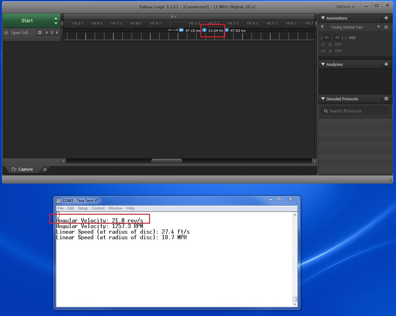
Figure 8. Checking the system’s accuracy against a Saleae logic analyzer. Click to enlarge
Summary, and Next Steps
As demonstrated in this article, determining both the angular velocity and linear speed of a spinning disc, with the use of an optical switch, is actually quite easy. The most difficult part was writing the firmware, but still, it wasn't all that hard.
The next step, in this two-part project, is to display the measured data on an LCD screen. A keypad will be used to cycle through the various measurements.
Give this project a try for yourself! Get the BOM.