 Facebook
 Google
 GitHub
 Linkedin
Build Your Own Low-Resistance Meter
This project will show you how to make a device that can measure resistances as low as 0.1 ohms.
Learn how to build your own low-resistance meter!
You probably already have a DMM for measuring resistance, but can it be used with resistances below 1Ω? And if so, are those low-ohm readings reliable?
This project will show you how to make your own low-resistance meter; it uses only a handful of components and can measure resistances as low as 0.1Ω.
Schematic
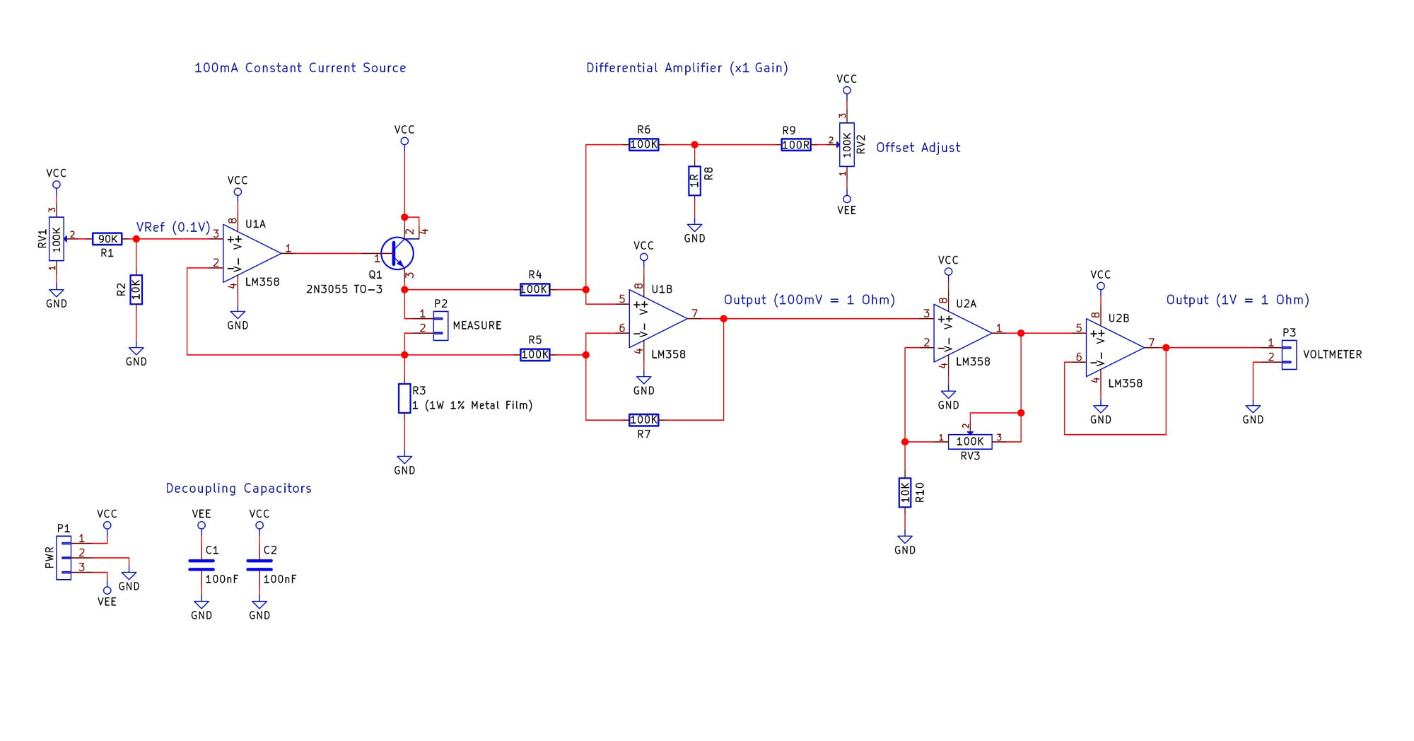
Click for larger image
The Theory
Measuring resistances can be done using a variety of methods (Wheatstone bridge, RC calculation), but in this project, the chosen method is to use the most fundamental equation in electronics:
$$V = IR$$
A constant-current source will establish the current through the resistance under test and measure the voltage drop that the resistance produces. This voltage drop will then be amplified and fed into a standard multimeter. The magnitude of the voltage will be equal to the resistance in ohms (e.g., 1V = 1Ω). We will need to select a current that produces reasonable voltages for the amplifier stages that follow the constant-current stage, and we can do this by using the above equation and inserting expected values for R (i.e., less than a few ohms).
One important consideration is the op-amp's input offset voltage, which is modeled as a voltage source in series with the op-amp's inverting or noninverting input terminal. This voltage is multiplied by the op-amp's noninverting gain, and it is a source of error because it can make the output voltage lower or higher than what we would expect from an ideal circuit. So we want to design our circuit such that the effect of this offset voltage will be minor. If your op-amp has offset-null functionality, you can use that to reduce the amplitude of the offset voltage, but we're using the LM358, which does not include offset-null pins. Instead, we can easily reduce the influence of the offset voltage by ensuring that the signal of interest is much larger than the offset voltage, which is ±2mV for the LM358.
Our goal is to measure resistance as low as 0.1Ω. This means that we have to choose a constant-current source that creates a voltage significantly larger than 2mV when the current is passing through a resistance of 0.1Ω. This is a trade-off, because higher currents have disadvantages and lower currents reduce the voltage drop across the resistance under test. The problems with higher current are the following:
- Higher power consumption, whereas lower power consumption helps with portability.
- Lower currents result in less heat generated by the constant current source circuit.
- Lower currents reduce the power dissipation and hence temperature increase of the resistance under test; with lower current, we can measure the resistance of circuit elements that are more susceptible to heat damage (thin wires, for example).
The current chosen for this circuit is 100 mA. This amount of current is not too high yet it generates 10mV across a 0.1Ω resistor, and 10 mV is adequate considering our ±2mV offset voltage.
The constant-current source consists of
- U1A – LM358
- Q1 – 2N3055 (TO-3 package)
- RV1 – potentiometer for adjusting the reference voltage applied to the op-amp's noninverting terminal
- R1 & R2 – divider (1V from RV1 corresponds to constant current of 100mA)
- R3 – sense resistor (1Ω, 1W, metal film, 1% tolerance)
- P2 – two terminals for connecting the resistance to be measured
With a constant current of 100mA through the 1Ω sense resistor, the power dissipation is 0.1W (hence the choice of 1W). Q1 will conduct 100mA as long as a resistance is connected to P2, and I chose the TO-3 package to ensure that the transistor does not overheat. The specific part used for Q1 is not that important as long as the transistor can handle 100mA of collector current and is NPN.
The next stage after the constant-current source is a differential amplifier with a gain of 1 and an offset voltage adjust. We are using a "differential" amplifier here because we want to detect the voltage drop across the resistance under test, i.e., the difference between the voltage on one side of the resistance and the voltage on the other side of the resistance.
The differential amplifier consists of
- U1B – the op-amp
- R4, R5, R6, and R7 – these resistors configure U1B as a differential amplifier
- R8, R9, and RV2 – offset adjust
The circuit consisting of R8, R9, and RV2 allows us to add an adjustable offset voltage to the output of the differential amplifier. This feature can be used to compensate for the op-amp's input offset voltage or other error sources. Please refer to the calibration section (below) for details on how to implement this compensation circuit.
The last stage is an amplifier with gain of 10. This additional gain sets the overall measurement ratio to the convenient value of 1:1, i.e., 1Ω of resistance produces 1V at the output.
- U2A, RV3, and R10 – noninverting amplifier with gain of 10 (RV3 set to 90K)
- U2B – output buffer
BOM (Bill of Materials)
|
Component Ident |
Value |
|
U1, U2 |
LM358 – DIP 8 |
|
R1, R4, R5, R6, R7 |
100K resistor |
|
R2, R10 |
10K resistor |
|
R3, R8 |
1R 1W metal film resistor, 1% tolerance |
|
RV1, RV2, RV3 |
100K linear potentiometer |
|
Q1 |
2N3055 BJT, TO-3 |
|
C1, C2 |
100nF decoupling capacitors |
Construction
How the circuit is constructed is up to you but here are a few ideas:
- Project box – Use an internal 9V battery and external connectors to keep the circuit in one small box.
- Multimeter attachment – Using a few banana plugs, you could create a circuit that fits directly onto a multi-meter.
- A meter – Going all the way, you could purchase a small voltage meter and house the whole project in its own package to make your own measurement device!
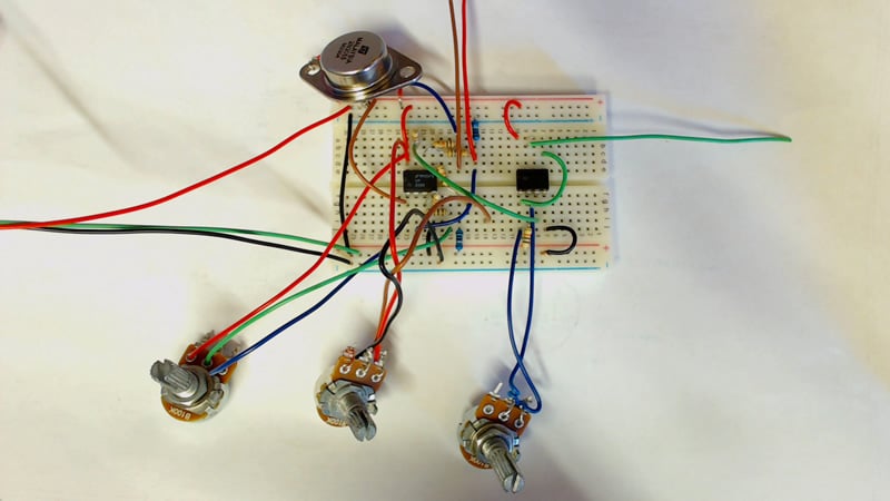
The low-resistance meter as a breadboard circuit.
The photo above shows the three potentiometers:
- the one on the left controls the constant-current source
- the one in the middle controls the differential amplifier offset
- the one on the right controls the gain of the output stage
The red, green, and black wires leaving the breadboard are for +5V, 0V, and -5V, respectively. The brown and red wires that go off toward the top of the image are for the resistance under test, and the green wire going to the right is for connecting the low-resistance meter's output to the input of a multimeter.
Note: You will need to ensure that the multimeter's common input is connected to the ground of the low-resistance meter.
Power
This circuit requires a split power supply for full functionality. However, note that the negative rail is used only in the circuit that adds an adjustable offset voltage to the output of the differential amplifier. If you can get adequate performance without this compensation circuit, the negative rail is not needed. If you're not using the LM358, keep in mind that the input common-mode voltage range of your op-amp must extend almost all the way to 0V, because we are dealing with input voltages near 100 mV.
The power-supply requirements are rather flexible (but don't exceed your op-amp's maximum supply voltage). You need to make sure that the power supply can source sufficient current (at least 200mA, considering that the current source alone requires 100mA). Also, be aware that the power dissipation of Q1 is proportional to the positive supply voltage, so keeping the input voltage as low as possible will reduce Q1's power dissipation.
I recommend ±5V supplies; for the negative rail you can use a Negative Voltage Generator.
Calibration
The first part of the circuit to calibrate is the constant-current source. The easiest method is to use a multimeter (connected to P2) to measure the constant current.
Adjust the value of RV1 until the measured current is 100mA. Start with RV1 adjusted to its minimum resistance. This minimizes the initial constant-current setting and thus prevents potentially harmful amounts of current through Q1 and R3; also, the resulting power dissipation will lead to increased component temperatures, and hot transistors can cause serious contact burns.
With the constant current set, we need to compensate for error in the output of the differential amplifier. You can do this by measuring a known resistance and then adjusting RV2 until the output of the differential amplifier corresponds to the known resistance (for example, a resistance of 1Ω should produce a differential output of 100mV), or you can measure the voltage across a small resistance using a precise voltmeter and then adjust RV2 such that the differential amplifier's output is equal to the measured voltage.
The final calibration step is to adjust RV3 so that the gain of the U2A amplifier is equal to 10. Measure the noninverting input voltage of U2A and adjust RV3 until the output is 10 times the value of the input.
Summary
With the circuit complete, you can now test your circuit to see if it is functioning correctly. If all goes well, you should now have a low-resistance meter that works in conjunction with an accurate multimeter.
So where could this be used? Personally, I built this circuit so that I could measure the resistance of mains wires (when dead, of course!) for some electrician practice. Instead of purchasing a very expensive electrical kit (costing at least $500), this circuit allows me to practice at a price of a few bucks.
This circuit can be used with a pair of small pogo pins to probe small PCB traces. It can also be used to measure contact resistance (which can sometimes cause issues in circuits that rely on mechanical contact).
Give this project a try for yourself! Get the BOM.
Related Content


Looks great! I may build this!