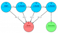
 Facebook
 Google
 GitHub
 Linkedin
DIY Arduino-Based Sous-Vide Machine
Learn how to build your own sous-vide machine. Say goodbye to overcooked steak!
Build your very own sous-vide machine and get perfectly cooked meals with high-precision temperature control. Grab your Arduino, a rice cooker, and a temperature sensor and let's get started.
Are you a foodie or simply just enjoy eating a properly cooked meal? If the answer is yes, you need to have a sous-vide machine in your life. They are very easy to build and maintain and the whole project can be done in just a weekend. This project is mostly dedicated to meat lovers, but vegetarians could also make use of this device.

What Is a Sous-Vide Machine?
First of all, you may be wondering what a sous-vide machine even is. The name isn’t that intuitive if you don't speak French (or even if you do). "Sous vide" is French for "under vacuum", which gives a hint about its purpose.
Traditionally, step one is to place the food to be cooked into a plastic bag and vacuum it closed. You then lower the bag into the machine, which is filled with water heated to a precise temperature. (As a note, you don't necessarily need to fully vacuum pack the food. You can just as easily put the food into an open bag and lower its bottom half into the machine, allowing the pressure of the water to remove the air around the food.)
This is a culinary method developed to essentially boil foods, especially meats, without losing juices or flavor into the water. But what's the benefit? Wouldn't it be better (and easier) just to cook a steak in a skillet?
The answer is simply “no” and I'll tell you why. Let’s presume that you enjoy your steak medium rare. When you cook it in a pan, the meat isn’t uniformly cooked because it is cooked from the outside in. This results in the middle being perfectly cooked and pink, but then moving farther away from the center it is more medium, and it might even be well done on the outside.
Now, if we cook the same piece of steak in a sous-vide machine, the piece of meat would be perfectly cooked all the way through. Here is a picture to better understand what is happening:

If you were not totally convinced this project was worth doing at the beginning, I hope this has changed your mind. Let’s stop here with the “why” and start building our sous-vide machine!
BOM
First of all, for our sous-vide machine to be as simple as possible, we will need a basic rice cooker. This contains our desired heater and the container for water. Without further ado, here is the complete BOM:
- Rice cooker
- Arduino Nano
- LEG-5 relay
- 2.2kΩ resistor
- 2N2222 NPN transistor
- MCP9701* thermistor IC
- 1N400x diode
- Push buttons (quantity 3)
- 16×2 LCD with a Hitachi HD44780 I2C controller
- 5V power supply
- Extension cord
- Epoxy**
- 100nF decoupling capacitor (recommended, but not essential)
*You could use a DS18B20 instead but you'd need to change the code accordingly
**For waterproofing the temperature sensor
The Hardware
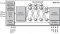
Let’s now talk about the hardware aspect of this project. Here is the schematic:

Please connect everything as you see in the schematic. Below I will try to explain why we chose the specific components and how they work.
MCU (Microcontroller Unit)
For the “brains” of this device, we will be using a very basic development board: the Arduino Nano. It has the same microcontroller, ATMEGA328, as the Arduino Uno, but in SMD form.
LCD
The LCD is a common 16×2 character display with a Hitachi HD44780 controller. Attached to it is an I2C board that also contains a potentiometer for contrast adjustment. I decided to use this because we will only need four pins to communicate with our Arduino: two for data and two for power.
Relay
The LEG-5 relay is a through-hole component that acts as a switch, closing when current is driven through the coil. You can use any other relay; just make sure that the nominal coil voltage is 5V and that it has an inductive AC contact rating at least 1.5 times greater than the current required by your rice cooker. For example, my rice cooker needs about 2A AC, and the LEG-5 relay has a rating of 3A.
In the schematic, there is also a diode in parallel (actually, strictly speaking, it is antiparallel) with the relay coil. This diode is called (among other names) a flyback diode, and it protects the transistor by providing a path for the inductive current that continues to flow after the transistor is turned off.

Another important aspect of this project is how to “tap into" the extension cord. (We're using an extension cord because we don't want to ruin the cord attached to the rice cooker.) We need to create a break in one of the extension cord wires and insert our relay.
Household electrical cables consist of “line”, “neutral”, and “ground”. In order to properly turn on or off the sous-vide machine, we need to insert a relay in the line conductor. We could put the relay in the neutral conductor, but it is good practice to use the line conductor because this approach can provide extra protection against electric shock. You can determine which is the line wire by using a mains tester (which usually looks like a screwdriver) or following the wiring color codes specific to your country. You can find more about color codes here. Another good practice is to use a double relay or two relays to switch both the line and the neutral.
Important note: When building this project, be careful with the mains voltage. Always make sure everything is unplugged when you are tinkering with the wires, and arrange the wiring such that it is impossible for the (exposed) line and neutral conductors to come into contact. If you aren’t 100% sure about what you are doing, please ask in the comments or in the forum before you continue with your project.
Continuing with the switching part of the schematic, you can see that there is an NPN transistor and a resistor there. This is to amplify the current needed to energize the coil of the relay. We need this because the current needed by the relay (72 mA) is greater than what our microcontroller can output (the absolute maximum I/O-pin output current is 40 mA, and typical operating currents should be significantly lower). The resistor is needed to limit the current going into the base of the transistor, which is intended to operate as a switch (i.e., in the saturation region). You can read more about this subject here and here.
Buttons
The switches are normal pushbutton switches that are closed only when they are pressed (they do not maintain that state after release). We do not need any external pull-up resistors because we will be using the microcontroller's internal pull-ups. For more information on switch types, go here.
Temperature Sensor
The backbone of this project is the temperature sensor, the MCP9701. I didn’t choose this particular device for any specific design reasons; it was just what I had available. It has decent accuracy, and the interface is straightforward—it outputs a voltage (Vout) proportional to the ambient temperature (Ta), with a slope (Tc, i.e., Temperature Coefficient) of 19.5 mV/°C and an offset voltage (V0°C) of 400mV.
\[V_{out} = (T_{c} \times T_{a}) + V_{0°C}\]
I suggest that when placing this sensor in the sous-vide, it should be in the center of the pot and at medium depth, or at least close to the plastic bag that contains the to-be-cooked item.
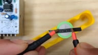
This temperature sensor is not waterproof, so we need to make it waterproof before we can use it for this project. To do this, we solder wires to it and then dip it in epoxy so that any conductive part is covered. Here is how mine turned out:

My waterproofed temperature sensor
If you don’t want to go through this trouble, you can use an already waterproofed sensor.
On the schematic, there is a decoupling capacitor, C1. My circuit worked well without it, but it's a good idea to include it.
Power Supply
Finally, the power supply! One 5V supply is used for the entire circuit. You should find something that can source at least 150mA. For example, a mobile phone charger will do the job.
Software
Now that we are done with the hardware, let’s look at the software.
You can see that there are two files : "main.ino" and "main.h". The header file, with the extension ".h", includes declarations for all the variables and constants used and also the "include" directives, because we are using two libraries, which you will need to install. The first one is the PID library by Brett Beauregard, which will be used to control the relay to obtain the desired temperature, and the second one is a library for controlling the LCD via I2C. If you wish to change parameters or what pins to use, you should do this in the header file.
In the "main.ino" file we find the basic Arduino functions "setup()" and "loop()". In setup() we initialize all the variables that need a default value and also set the pins as either output (for the relay) or input (for the switches).
In the main loop we call five functions:
- cook(): We call this function only if the variable "start" is set to "true" and if the elapsed time since the start of cooking is less than the chosen cooking time. Inside this function the "magic" happens. We read the temperature via the "read_temp()" function and we pass it to the PID controller, which will give us an output. Based on this output, we set the relay-control pin to either "HIGH" or "LOW". A PID controller is a feedback system that calculates an output value based on the error, which is the difference between the setpoint (our desired temperature) and the current temperature, and three constants referred to as P (proportional), I (integral), and D (derivative). To learn more about PID control, take a look at one of my previous projects, Do-It-Yourself Soldering Station with an ATmega8. In the sous-vide project, we use the output to control the "on time" of the relay, because the relay can only be on or off (2 values).
- checkBacklight(): This function verifies if any button has been pressed in the last 30 seconds. If not, it will turn the backlight off.
- updateButtons(): Here, the current state of the buttons is checked.
- checkMenu(): Could also be called the "menu function"; it uses multiple switch statements to navigate around the menu and set the temperature and cooking time using the three buttons.
- updateDisplay(): Lastly, we update the LCD to display the main menu and parts of it or the current temperature and remaining cooking time (if the sous-vide cooking process is underway).
- read_temp(): This one is not directly called in the main loop, but it is a very important function. It makes 5 readings in the beginning (in the setup() function) and after that, in the main loop(), it subtracts the last reading, adds another one, and calculates an average. What this basically does is smooth our input data. You can learn more about this on this Arduino page. The averaged value is then converted to degrees Celsius using the formula presented to you above in the "Temperature Sensor" section. We convert the reading from the 10-bit ADC to millivolts, then we subtract 400 (the offset), and then we divide by the slope in mV/degree (i.e., 19.5) to obtain the temperature in degrees Celsius.
double realtemp = ((average * (5000.0 / 1023.0)) - 400) / 19.5;
Conclusion
That’s it, guys! If you have followed the instructions step-by-step, go and prep your meal now because the sous-vide machine is ready for action, and I'm sure that you are hungry.
Turn it on, enter the menu, set the temperature, set the cooking time, press start, and enjoy! Here is my try at a sous-vide burger:

If you have any questions or ideas for improving the project, please don’t hesitate to leave a comment. I will try to maintain the project on this GitHub page if you want the latest version of the software, but I cannot guarantee that the information you find here will still be 100% accurate. If you don't need extra features, use the code included in this article.
What I didn’t mention (because I wanted to keep this project as simple as possible) is a water pump. All professional sous-vide machines have a water pump that circulates the water and thus helps to maintain uniform temperature. A pump is not necessary, but if you have one available, you might want to try it and see if the results are noticeably improved. You can use an Arduino output pin in conjunction with a transistor to turn it on.
Here is a link to a web page that gives the best temperatures for different types of meat. You can also look around on YouTube if you need an idea for a sous-vide meal.
Thanks for reading!
Give this project a try for yourself! Get the BOM.


Great project. The only question I have is water boils at 212 degrees. How does the food (Meat) get hot enough to cook? It might be handy to have a 2nd thermister to place inside the food to know when it has reached a desired temperature when trying to establish a rare, medium rare, medium, etc. end result.
Ummmm… just an observation or I’m missing something. I do not see any link to the actual code.