 Facebook
 Google
 GitHub
 Linkedin
How to Build a Weighing Scale Using a Load Cell and a Microcontroller
In this project, we're making a weighing scale using a C8051 microcontroller development kit, a load cell, and the Simplicity Studio IDE. The measured weight will be displayed on an LCD screen.
In this project, we'll build a weighing scale using a C8051 microcontroller development kit, a load cell, and the Simplicity Studio IDE. The measured weight will be displayed on an LCD screen.
LCD Display
The LCD used in the project is part of the Silicon Labs CP2400DK development kit.
.jpg)
Figure 1. Silicon Labs CP2400DK development kit (C8051 microcontroller and LCD controller). Image courtesy of Digi-Key.
The manufacturer part number of the LCD device itself (figure 2) is VIM-878-DP-RC-S-LV. If you include the decimal point and the apostrophe (for each digit), this "14-segment" LCD display becomes a 16-segment display. And when summing all the 16-segments of the eight digits together, we see a total of 128 segments. Such a 128-segment display mandates the use of a 128-segment driver, and Silicon Labs has decided to use driver p/n CP2400 (Figure 3).

Figure 2. LCD screen with 16 segments for each of the eight digits (total of 128 segments). Image courtesy of Digi-Key.

Figure 3. 128-segment LCD driver. Images courtesy of Silicon Labs (pages 1 and 22).
Load Cell
The load cell that I chose to use is made by Uxcell, model # a14071900ux0057.

Figure 4. Load cell. Image courtesy of Amazon.
This particular load cell is commonly referred to as a straight bar load cell or a parallel beam load cell. Such load cells are typically available in many rated loads (i.e., maximum loads); the one utilized in this project is rated for a maximum weight of 10kg (or 22 pounds). Its advertised rated output is 1±0.15mV/V. This means that when the load cell has its maximum rated weight applied (10kg in this case), then the output voltage will be 1mV (±0.15mV) per every 1V applied to the load cell's excitation (see figure below). And when I say the voltage is "applied to the load cell", the voltage is actually being applied to the Wheatstone bridge strain gauge's excitation leads. Similarly, it's the Wheatstone strain gauge the produces the output voltage (see figure below).

Figure 5. The load cell's Wheatstone bridge strain gauge schematic.
For this project I'll be applying 5.0VDC as the excitation; therefore, when a 10kg load is applied to the load cell, its VOUT will be 5.0mV (±0.75mV). And because 5.0mV is such a small voltage, it will need to be amplified prior to being sent to the microcontroller.
Side note: Some microcontrollers—not the one used in this project—have differential ADC inputs; single-ended inputs are considered standard for most microcontrollers. When using a microcontroller with a single-ended ADC input and when the sensor in question provides a differential output signal, a differential amplifier must be utilized. This type of amplifier converts a differential signal into a single-ended signal that can be measured using a standard single-ended ADC.
Instrumentation Amplifier
The differential amplifier that I chose to use is actually called an instrumentation amplifier, or in-amp. I began this project using the INA126PA in-amp from Texas Instruments—I purchased this device from Digi-Key for $3.15. However, when it failed to perform as advertised and after troubleshooting it for about an hour, I decided to move to Plan B: use the AD627 (from Analog Devices), which I had also purchased. I bought this part—quantity one—from Digi-Key for a whopping price of $8.45! I had no idea that these in-amps cost so much money! Fortunately, this device worked flawlessly. Hence, I think I'll be using in-amp devices from Analog Devices in the future as opposed to TI parts, although generally speaking, I'm a fan of parts, and prices, from TI. Setting the gain for both of these in-amps is simple: all that’s required is one external resistor. Also, both the TI and the Analog Devices part are advertised as single- or dual-supply devices, and I much prefer to use a single-supply.
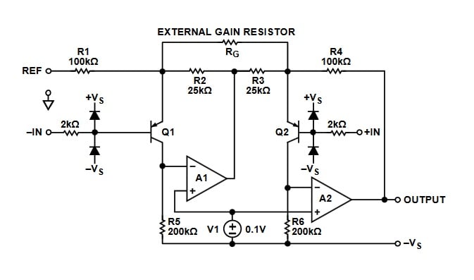
Figure 6. Analog Devices instrumentation amplifier (AD627) simplified schematic. Image courtesy of Analog Devices (page 14).
| Item # | Description / Source | Cost (each) | Other Information |
|---|---|---|---|
| 1 | C2400DK development kit | $148.75 |
User Guide |
| 2 | Breadboard | $8.98 | or equivalent |
| 3 | Jumper wire kit | $6.20 | or equivalent |
| 4 | 10kg load cell | $8.14 | or equivalent |
| 5 | Instrumentation amplifier | $8.45 | Datasheet |
| 6 | 1 kΩ potentiometer | $2.41 | Datasheet |
| 7 | Machine Screws (M4-0.7 x 25mm). Qty 2 |
$0.76 | or equivalent |
| 8 | Machine Screws (M5-0.8 x 25mm). Qty 2 |
$0.76 | or equivalent |
Making the Connections / Schematic
The microcontroller uses the SPI interface (SPI channel 1) for communicating to the LCD driver—figure 7 below shows Simplicity Studio's hardware configuration GUI for how the C8051's SPI is configured.
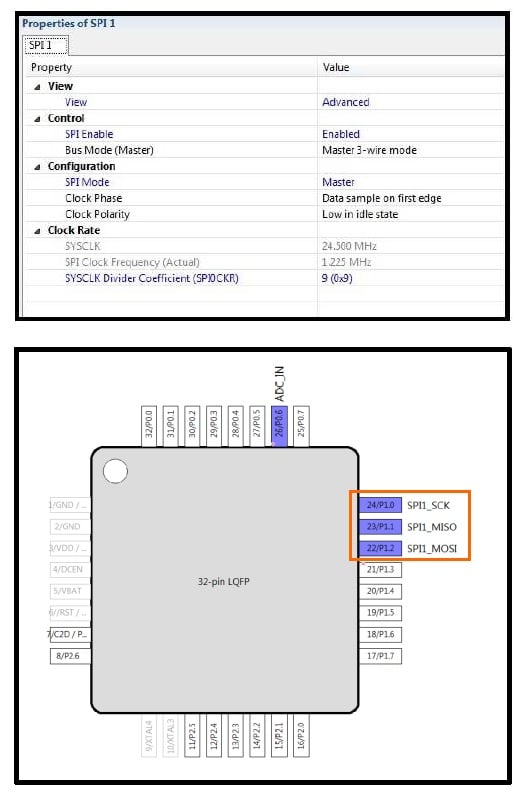
Figure 7. SPI interface configuration
Choosing the Gain for the Instrumentation Amplifier
As mentioned before, the excitation voltage applied to the load cell is 5.0VDC, which will produce an output voltage of 5mV (at full load of 22 lbs). Though the microcontroller's ADC has an input range of 0 to 3.30VDC, I want 3.00VDC to correspond to the full load (22 lbs). This will provide some headroom for the load cell's overload, which is 120% of full load, or 26 lbs. Given these conditions, I can calculate the necessary gain for the in-amp, and then choose the appropriate value of the gain resistor (RG).
$$5mV*Gain=3000mV$$
$$Gain = \frac{3000mV}{5mV}=600$$
RG equation (per AN627 datasheet page 22):
$$R_G = \frac{200k \Omega}{Gain-5}$$
$$R_G = 336 \Omega$$

Figure 8. Connection diagram. It's important that the decoupling capacitor (C1) be placed as close to the AD627's power pin as possible. Click to enlarge.
Configuring the Microcontroller Development Kit
Prior to powering up the microcontroller development kit, after all the connections have been made, be sure to configure it as follows:
Jumpers:
- J11: VBAT to WALL_PWR
- J12: VDD to VIO
- J17: VBAT_PIN to VBAT
Switches:
- SW4: set to "2 CELL"
- Power switch (SW5) to "OFF" position
Cables:
- Connect the ribbon cable debug adapter to J9
- Connect the USB debug adapter to your PC.
- Apply 5.0VDC to connector P2.
Attaching the Load Cell Base Plates
The load cell itself has holes with, to my surprise, screw threads. This makes it very handy when attaching the load cell to base plates. Again, to my surprise, one set of holes is larger than the other. Hmmm, I'm not sure why the manufacturer did this but, nonetheless, I was able to find the appropriate screws at the local hardware store.
- Quantity two: machine screws, M4-0.7 x 25mm
- Quantity two: machine screws, M5-0.8 x 25mm
- Note: the length of these four screws (25mm) is dependent upon the thickness of the spacers and of the base plates themselves.
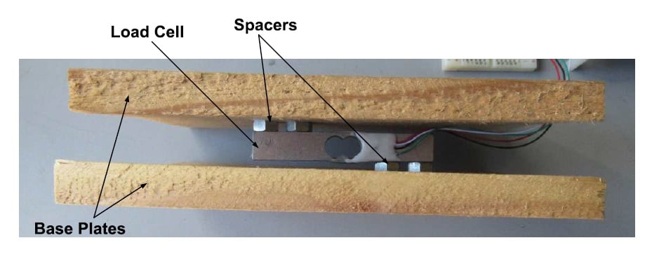
Figure 9. Load cell mounted to base plates. Click to enlarge.

Figure 10. The completed load cell system (sans 5VDC power supply). Click to enlarge.
The Firmware
Similar to another project of mine (Adding an LCD and Keypad to a Tachometer and Speedometer), for this project I heavily leveraged Silicon Lab's example LCD project (CP240x_LCD_Example), which made my firmware-writing task much easier.
The output of the in-amp is connected to port 0.6, which is the input to the microcontroller's ADC. Below is a list of features/goodies that I've incorporated into the firmware:
- The firmware takes and averages 200 samples of the measured voltage prior to sending the data to the LCD screen.
- If the applied load is greater than or equal to 23 lbs, the LCD will display "OVERLOAD."
- When the system is first energized, the firmware will display the tare weight (i.e., the weight at startup becomes the zero weight).
- The LCD is configured to display one digit following the decimal point.
   //----------------------------------
   // Main Application Loop
   //----------------------------------
   while (1)
   {

         //-----------------------------------------------------------------------
         // Measure Analog Value
         //-----------------------------------------------------------------------
         //
         // Take ADC conversion.
         //

         // Initiate a Conversion
         AD0INT = 0;                         // clear ADC0 conv. complete flag
         AD0WINT = 0;                        // clear window detector flag
         AD0BUSY = 1;                        // initiate conversion

         // Wait for conversion to complete
         while(!AD0INT);


         //                           Vref (mV)
         //   measurement (mV) =   --------------- * result (bits)
         //                       (2^10)-1 (bits)

         mV =  ADC0;
         mV *= VREF;
         mV /= 1023;
         lbs = (float) (mV * 22.0 / 300.0); // The multiplying factor is actually 22lbs/3000mV, but 300
					    // is used for displaying one digit after the decimal point.
         if(zero_scale == 0)		    // Used for zeroing the scale during power-up.
         {
        	 zero_offset = lbs;
        	 zero_scale = 1;
         }
         lbs = (lbs - zero_offset);
         AverageAccumulator += lbs;	    // Add the current lbs measurement to the accumulator.
         AverageMeasurements--;		    // Decrement the measurement counter.
         if(AverageMeasurements == 0)
         {
			// Calculate the average value: divide the summed AverageAccumulator by the
			// number of measurements.
			lbsAverage = (AverageAccumulator / 200.0);


			AverageAccumulator = 0;	   // Reset
			AverageMeasurements = 200; // Reset
			if(lbsAverage >= 230)	   // If the measured weight is greater than equal to
						   // 23.0 lbs, then display "OVERLOAD" on the LCD screen.
						   // The load cell is rated at 10kg (or 22 lbs), with
						   // safe overload of 120%, or 12kg (26 lbs).
			{
				sprintf(display_string, "OVERLOAD");
			}
			else sprintf(display_string, "d lbs ", (unsigned int) lbsAverage);
         }

         //-----------------------------------------------------------------------
         // Update LCD
         //-----------------------------------------------------------------------
         //
         // Update the LCD Display
         //
         LCD_OutString(display_string);
   }
All the code for this project can be downloaded from the link below.
Building and Loading the Code, and Verifying the Accuracy of the Scale
Load_Cell-Weight_Scale_AAC.zip
After downloading, building, and loading the code, I used my kitchen scale as a reference/comparison for taking weight measurements. As seen in the video (below), I place various weight samples (my old textbooks from college!) first on the kitchen scale and then on the load cell system. And as you can observe, both scales are extremely close in their displayed measurements.
Next Steps for Making a Real Product
If you, or I, decide to make an actual weight-measuring system based on this project using a customized PCB design, be sure to follow the grounding and layout recommendations as described in the datasheet (page 20). Also, replacing the wooden base plates with metal plates would increase the stability and robustness of the physical design.
Happy weighing!
Give this project a try for yourself! Get the BOM.


I think it’s wrong of you to say something was wrong with the TI part without clearly stating what it was, or that it could have been the way you used it.
I have no connection with TI but such vague statements and conclusions are very wrong.
How can you write an article about load cells and not mention the HX711? 😊 They can be had on eBay soldered onto breakout boards for about $0.75 each - shipped! NodeMCU even has an HX711 library that can read out the values from an ESP8266 via LUA script. Check out https://nodemcu-build.com