 Facebook
 Google
 GitHub
 Linkedin
How to Build Your Own Discrete 4-Bit ALU
In this project, we will build the heart of a simple 4-bit CPU, the ALU (Arithmetic Logic Unit).
Learn about the heart of a simple 4-bit CPU, the ALU (Arithmetic Logic Unit), and how to build one, yourself.
Believe it or not, computers existed before microcontrollers and CPUs were around. They used to be built using discrete parts including simple ICs and transistors.
CPUs are arguably the center of modern electronics, whether it be a mobile device or a control circuit for a factory. With so many types of CPUs on the market (RISC, CISC, etc.), it can be difficult—if not impossible—to keep up. But how do CPUs work? What goes on inside?
In this project, we will look at the mathematical core of a CPU—the ALU. Then we'll build one!
The ALU—Arithmetic Logic Unit
A CPU consists of three main sections: memory for variables (registers), control circuitry (microcode), and the ALU. The ALU (Arithmetic Logic Unit) is the part of a CPU that actually does calculations and condition testing.
For example, if you wish to add two binary numbers, it is the ALU that is responsible for producing the result. If your program needs to execute some code if two values are equal it is the ALU that performs the comparison between the values and then sets flags if the condition is met or not.
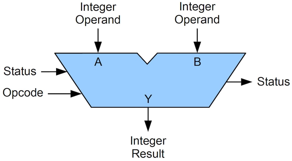
Representation of an ALU. Image courtesy of Jim Lamberson via Wikimedia Commons.
Modern CPUs consist of millions of transistors (even billions now!) and cannot possibly be duplicated at home. But a simple CPU (say, a Z80, for example) has only 8500 transistors. Computers in the past (such as many of the IBM mainframe computers) were actually built with discrete 4000 and 7400 series chips.
This means that you can build a CPU at home! So why not?
This project will be a discrete 4-bit ALU that will be constructed with 4000 series and 7400 series chips.
Project Prerequisites
Because this project is rather complex you will need the following:
- Basic understanding of boolean concepts
- Basic understanding of logic gates
Binary Addition
Two fundamental ALU operations are addition and subtraction.
The Theory
Adding binary digits (individual bits) is rather easy and is shown in the list below (all the possible combinations):
- 0 + 0 = 0
- 0 + 1 = 1
- 1 + 0 = 1
- 1 + 1 = 10 (This is also 0 + carry bit)
But how do we add binary numbers that are more than one digit long? This is where the carry bit comes into play and we need to use long addition.
Carry bits are used as shown below where "0(c)" means "no carry bit" and "1(c)" means "carry bit".
- 0 + 0 +0(c) = 0
- 0 + 1 +0(c) = 1
- 1 + 0 +0(c) = 1
- 1 + 1 +0(c) = 10
- 0 + 0 +1(c) = 1
- 0 + 1 +1(c) = 10
- 1 + 0 +1(c) = 10
- 1 + 1 +1(c) = 11
If we wish to add 10 and 10 in binary form, we would start by writing them down in the form of long addition. We add the bits up in columns using the rules above starting from the far right and moving to the left. When we have a carry from a bit addition, we move it one column to the left, where it gets included in the addition as a bit.
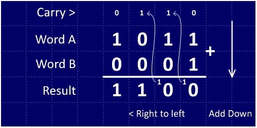
Long addition of binary numbers
In this example, we are adding 1011 and 0001 (11 + 1 = 12). Starting from the far right we add 1 + 1, which gives us 10 (0 and a carry bit). Then we move to the next column (the second from the right) and add all the bits. Notice how the carry bit is also included in this addition operation. This means we are adding three digits: 1 (the carry bit), 1, and 0.
For more information about Boolean arithmetic, check out this section of the AAC textbook.
So now that we can see how to add two binary numbers on paper, let’s see if we can make a circuit that adds two binary bits!
The Circuit
The half adder has two inputs and two outputs as shown in the diagram below. The two inputs represent two individual bits, the Sum output represents the sum of the two bits in the form of a single bit and the Carry output is the carry bit from the addition.
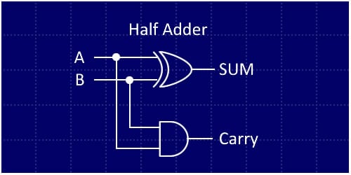
Half adder circuit , which uses an AND gate and an exclusive-OR (XOR) gate
| A | B | Sum | Carry |
| 0 | 0 | 0 | 0 |
| 0 | 1 | 1 | 0 |
| 1 | 0 | 1 | 0 |
| 1 | 1 | 0 | 1 |
Truth table for half adder
But what is wrong with this circuit? This circuit cannot take in a carry from a previous operation! So how do we fix this? Well, this circuit isn’t called a half adder for nothing! If we use two of these adders and an OR gate, we can create a full adder that has two bit inputs, a carry in, a sum out, and a carry out.
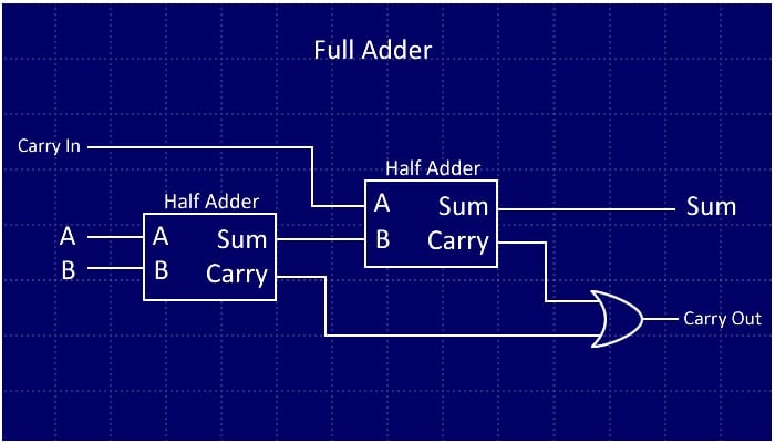
A full adder made by using two half adders and an OR gate
Unfortunately, for the 4-bit ALU, it would be impractical to use discrete chips to create a 4-bit adder. So we will cheat and use a 4008 4-bit adder IC. You can pick these up for a few dollars on eBay:
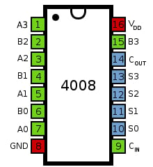
4008 4-bit full adder pinout. Adapted from this image.
Binary Subtraction
The Theory
Now that we can add two 4-bit numbers, how do we subtract binary numbers? To do this, we will implement a binary system called “two’s complement”. The system has a few rules:
- To negate a number (e.g., change 5 into -5), flip all the bits and add 1.
- A number is negative if the MSB (most significant bit) is 1. For example:
- 10010 is negative
- 00010 is positive
Note that by following rule 1 you can determine the value of a negative binary number:
- 0001 = 1: Negate this = (1110 + 1 = 1111) = -1
- 1001 = -7: Negate this = (0110 + 1 = 0111) = 7
- 0110 = 6: Negate this = (1001 + 1 = 1010) = -6
The two’s complement technique is beneficial because it allows us to perform both addition and subtraction using the same adder circuit. So if we wish to turn our 4-bit adder into a 4-bit adder/subtractor, we just need to incorporate a single 4070 IC (quad XOR). We feed the binary number inputs into one input of each XOR gate, use the other XOR input as an add/subtract line, and then feed this same line into the carry in of the adder.
When we wish to subtract B from A, we make the subtract line high. This does two things:
- Flips all the incoming bits on input B
- Adds one to the adder
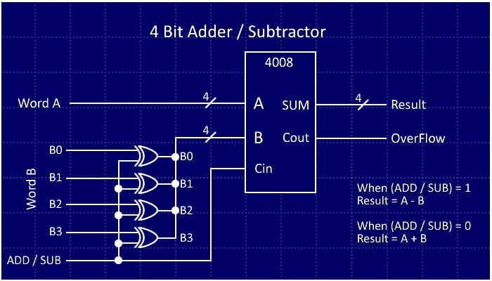
The complete 4-bit adder/subtractor
The final circuit will also use a 74HC125 quad buffer on the output so that the adder/subtractor unit can be connected to a common data bus for the output. The buffer also has an enable line that allows us to choose the output from the adder/subtractor.
With the adding/subtracting unit done, it's time to look at the logical functions.
Logical Functions
Logical functions are useful when bit manipulation is needed. Imagine a microcontroller that has an 8-bit port, and you use the lower 4 bits to read from a 4-bit data bus. When you read from the port you will need to remove the upper four bits, as those bits can affect program execution. So to remove these bits, you can mask them out with a logical AND function.
This function will AND bits from one word (the port) with another number (the number that will remove the upper four bits). If we AND the port with 0x0F (0b00001111), we preserve the lower four bits (because x AND 1 = x) and remove the upper four bits (because x AND 0 = 0).
- AND is used to remove bits
- NOT is used when you need to flip all the bits (0000 will become 1111)
- OR is used to merge bits (0110 OR 0001 is 0111)
- XOR is used to flip selected bits (0101 XOR 0100 is 0001)
The logical units in our ALU are AND, OR, XOR, and NOT gates connected to buffers. An enable line feeds into each bus buffer for each logical unit so that each unit can be selected individually.
- 4081 - Quad AND gate
- 4070 - Quad XOR gate
- 4071 - Quad OR gate
- 4049 - Hex NOT gate
- 74HC125 - Output buffers (for bus isolation)
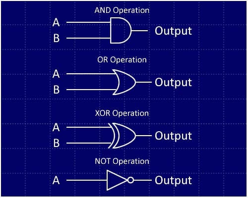
Logic gates showing the four logical functions of our ALU
Note:
- A and B represent bit 0, 1, 2, or 3 from word A and the corresponding bit from word B.
- NOT operations involve only one word; each bit in the word is complemented, regardless of the state of the other word.
Bit Shifting & Comparisons
Bit shifting is also a very important function. These functions are commonly found in microcontrollers with serial ports where data is streamed in bit by bit. This means that, as the bits arrive, you need to take that bit, place it in some byte at the beginning (or end), and then shift all the bits in the byte either left or right (depending on where you put the incoming bit).
Interestingly, a bit shift to the right (e.g., 0010 becomes 0001) is equivalent to division by two, and a bit shift to the left (e.g., 0010 becomes 0100) is equivalent to multiplication by two.
Bit shifting can be done quite easily. The only chip needed is a buffer because the physical data lines are simply rearranged.
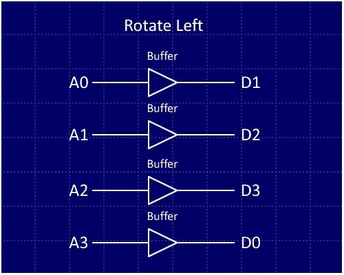
Rotate left
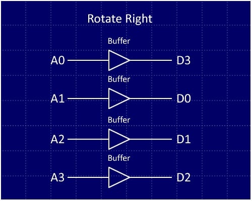
Rotate right
For a rotate left:
- Bit 0 is connected to bit 1 on the output
- Bit 1 is connected to bit 2 on the output
- Bit 2 is connected to bit 3 on the output
- Bit 3 is connected to bit 0 on the output
For a rotate right:
- Bit 0 is connected to bit 3 on the output
- Bit 1 is connected to bit 0 on the output
- Bit 2 is connected to bit 1 on the output
- Bit 3 is connected to bit 2 on the output
The last operation to be implemented in the ALU is the comparison, which is very useful (and easy to add). We will employ the 4585 magnitude comparator; what this chip does is take two 4-bit numbers and tell us whether A > B, whether A < B, and whether A = B.
This is useful because it makes implementing "if" instructions much easier. A lot of old processors do not have magnitude comparison abilities. This meant that trying to determine if a number was greater than or less than another number was less trivial—a subtraction could be done followed by checking the sign bit, but that makes the code less clear. In this ALU all you would need to do is just have the two numbers on the data bus and the magnitude comparator will tell you immediately if the two numbers are equal, less or greater.
The disadvantage of the 4585 comparator is that it is a magnitude comparator and does not work with two's complement.
A 4585 magnitude comparator. Image courtesy of datasheet-pdf.info.
BOM - Bill Of Materials
| Component | Quantity |
| 4008 (16 DIP) | 1 |
| 4081 (14 DIP) | 1 |
| 4070 (14 DIP) | 2 |
| 4071 (14 DIP) | 1 |
| 4049 (16 DIP) | 1 |
| 74HC125 | 7 |
| 100nF Capacitors | 14 |
| 14 DIP Socket (for soldering the project) | 11 |
| 16 DIP Socket (for soldering the project) | 3 |
Besides these crucial components, you will also need a method of creating the circuit. Personally, I prefer using a stripboard because it makes a more permanent circuit. However, you could use a breadboard for faster prototyping or even design a PCB.
Putting It All Together!
Below is a link to a schematic for the ALU (in PDF format); it is rather large. But do not be put off by this schematic because building the ALU is actually quite easy.
Instead of trying to build the whole module on one board, build the ALU in smaller sections which glue together via bus wires.
My ALU was built on four separate stripboards which all fit on a custom mini shelf (also made of stripboard).
- The front-side buses (left panel in the image) are the inputs A and B
- The back-side buses (right panel in the image) are the data output and the function selection
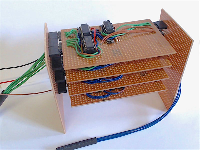
The completed ALU. Four shelves and plenty of wires!
To control the ALU for testing purposes, a fifth stripboard was used to hold the buttons for inputs, LEDs for outputs, and a 4515 decode chip to decode the outputs.
The modules on the ALU have enable lines that are active-low; so to enable a module on the data bus, you have to connect the enable line to 0V instead of 5V. 5V stops the module from sending any data.
IMPORTANT NOTE
The ALU uses a common data bus where the individual functions are isolated via a quad buffer. However, it is imperative that only one module is functioning at a time (e.g., only ADD is enabled and all others disabled). Enabling more than one module at a time will result in damage to the 74HC125 chips.
ALU in Action!
Summary
With the ALU completed, we can now mathematically and logically process two 4-bit numbers. But this ALU is only a small piece of the puzzle!
For our next steps, we could attach a register to the output of the ALU and feed it back into word B. Then we could create a memory controller that could stream numbers from a chip and perform operations on those numbers. It would be at this point that we could make those numbers stored in memory decide what operation the ALU will do.
This is where it stops becoming an ALU and becomes a simple CPU!
For those who wish to take this project further, here are some resources to help:
Give this project a try for yourself! Get the BOM.


Impractical to build this adder with discrete parts? It’s impractical to build this at all!
As an engineer who built such things from discrete parts long ago for real production systems, I have no issue whatsoever building them again with discrete parts. So to be really helpful, write an article that actually does what the title purports to do!