 Facebook
 Google
 GitHub
 Linkedin
Make a Wireless Thermometer with Arduino
Learn how to use a 433MHz RF module with an ATMega 328P-PU. In this article, we'll make a circuit with a DHT11 sensor and a RF transmitter. We'll also make a receiving circuit with a 433MHz RF receiver and an LCD display.
Learn how to use a 433MHz RF module with an ATMega 328P-PU. In this article I will make a circuit with a DHT11 sensor and a RF transmitter. I will also make a receiving circuit, with a 433MHz RF receiver and an LCD display.
Requirements
- A computer running Arduino IDE. (I'm using v 1.6.5)
- VirtualWire library (Link below)
- Arduino Mega
- ATMega328p
- AVR MKII ISP programmer
- An LCD display
- DHT11
- 433MHz RF modules (Transmitter and receiver
- Jumper wires
- Breadboard
- Parts according the parts list below
Introduction
In this article I will show you how to make a circuit that measures temperature and relative humidity and send those measurements with an off-the-shelf 433MHz RF module. The temperature and humidity sensor is the DHT11. You can read another article about the sensor here.
There are many ways you can send small amounts of data with an Arduino or other ATMega-microcontrollers. One of them is using an already-made library like RCSwitch, Radiohead, or VirtualWire. It is also possible to send raw data with the microcontroller's built-in UART feature. Using the built-in UART is not recomended because the receiver will pick up all kinds of noise, so the microcontroller will not act the way you want it to. In this article, I am using the VirtualWire library to transmit and receive data. The library works with Arduino IDE 1.6.2 and 1.6.5.
The 433MHz transmitter module will oscillate and transmit noise when it is not transmitting data. It might also interfere with other RF applications. To prevent that from happening, I am turning it on when it transmits, and turning it off when it is not transmitting.
*Note that all code is in zip form at the bottom of this article
Hardware
We need 2 block diagrams. One for the transmitter circuit and one for the receiver circuit.
The transmitter:
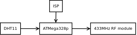
I want:
- A way to program the microcontroller -> ISP
- A sensor to measure temperature and humidity -> DHT11
- A microcontroller to process the data -> ATMega328p
- A way to send this wireless -> 433MHz RF module
The receiver:

I want:
- A way to receive the RF signal -> 433MHz RF module
- A way to process the received data -> Arduino Mega
- A way to display the temperature and humidity -> 16x2 LCD
Schematic diagrams
Transmitter (click for larger image):
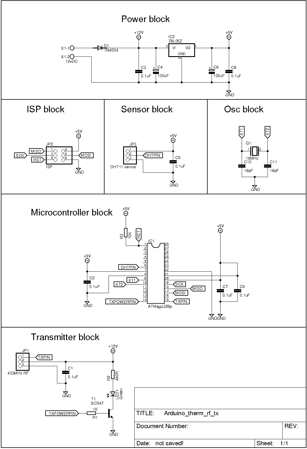
In this example, I am not going to tie the unused pins on the microcontroller to a pad for further development. This will only be made on a breadboard.
Receiver:

Please note that the receiver is an Arduino Mega, and it is not in the schematic. Follow the labels on the schematic to connect to the Arduino Mega.
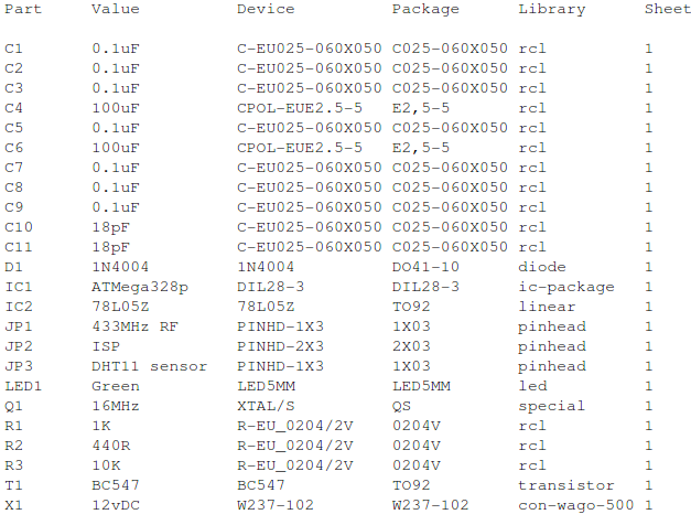
Parts list
Transmitter:
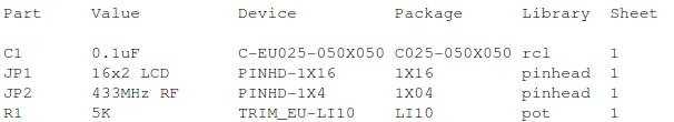
Receiver:
Software
First is the transmitter software:
// Include needed libraries
#include
#include

// Defininition
#define dhtPin 4
#define dhtType DHT11
#define txPowerPin 8

// using the DHT library
DHT dht(dhtPin, dhtType);

// Variables
char msg0[3];
char msg1[3];

int tem = 0;
int hum = 0;

// Setup function - run one time
void setup() {
  pinMode(txPowerPin, OUTPUT);
  pinMode(txPowerPin, LOW);
  vw_setup(4800);     // VirtualWire communication speed
  vw_set_tx_pin(9);  // VirtualWire transmit pin
}

// Loop function - runs forever
void loop() {
  digitalWrite(txPowerPin, HIGH);
  hum = dht.readHumidity();             // Variable holding humidity
  tem = dht.readTemperature();          // Variable holding temperature
  itoa(hum, msg1, 10);                  // Converting humidity to an array of chars
  itoa(tem, msg0, 10);                   // Converting the temperature to an array of chars
  strcat(msg0, msg1);                    // Adding/joining the two arrays
  vw_send((uint8_t *)msg0, strlen(msg0)); // Sending the msg
  vw_wait_tx();                         // Wait for tx to finish

  digitalWrite(txPowerPin, LOW);

  delay(5000);                          // Wait five seconds and it again

}
To send the humidity and the temperature in one single send statement, I join them together since this is one-way communication. First, the data is read into the variable as integers, then the integers are converted to an array of characters, and finally they are joined together. On the receiver side, the data will be split into single characters. By doing it this way, I am limiting myself to 2 digit degrees. If the sensor is in an environment with less than 10oC, I will get some rubbish characters on the display. For example, if the temperature is 20oC and the humidity is 45%, it sends 2045, which is fine. If the temperature is 9oC and the humidity is 78%, it sends 978x, where the x represents a random character. I challenge the reader to change the software to send the right data when temperature is less than 10oC.
Receiver software:
// Include needed libraries
#include
#include

// Definitions for the LCD connections
#define RS 9
#define E 10
#define D4 5
#define D5 6
#define D6 7
#define D7 8

LiquidCrystal lcd(RS, E, D4, D5, D6, D7);

// "Drawing" the degree symbol
byte degreesymbol[8] = {
  B01100,
  B10010,
  B10010,
  B01100,
  B00000,
  B00000,
  B00000,
  B00000
};

// Variables
int tem = 0;
int i;

// Setup function - run one time
void setup() {
  lcd.begin(16,2);                  // Defining the LCD
  lcd.createChar(1, degreesymbol);  // Creating the degree symbol at place 1
  Serial.begin(9600);              // For debugging purpose
  vw_setup(4800);                  // VirtualWire communication speed
  vw_rx_start();                   // Getting redy to receive
  vw_set_rx_pin(2);                // VirtualWiore receive pin
  lcd.clear();                     // Clear the LCD
}

// Loop function - runs forever
void loop() {
  uint8_t buf[VW_MAX_MESSAGE_LEN];      // Variable to hold the received data
  uint8_t buflen = VW_MAX_MESSAGE_LEN;  // Variable to hold the length of the received data
  lcd.setCursor(0,0);
  lcd.print("Temp: ");
  if (vw_get_message(buf, &buflen))    // If data is received
  {
    for (i=0;i<2;i++)               // Get the two first bytes
  {
  Serial.write(buf[i]);                // Debugging purpose
  lcd.write(buf[i]);                   // Write the first bytes on the LCD
  }
  Serial.println();                    // Debugging purpose
  lcd.write(1);                        // Write the degree symbol on the LCD
  lcd.print(" C");
  lcd.setCursor(0,1);
  lcd.print("Hum:  ");
    for (i=2;i<4;i++)              // Get the two last bytes
    {
      Serial.write(buf[i]);                // Debugging
      lcd.write(buf[i]);                    // Write the last bytes on the LCD
    }
  lcd.print("% RH");
  }
}
A fun way of using the LiquidCrystal library is to make custom characters. With the createChar, I made the degree symbol. With the same technique, you can make your own symbols. To make a custom symbol or character, you declare it as a byte, and "draw" the pixels that will be on. 1 is on and 0 is off.
In the setup() function you create it with createChar. createChar takes two arguments: a position to hold the number of the character and the name of the character you create. In my case it is: lcd.createChar(1, degreesymbol); The symbol is then sent to the lcd display with the lcd.write-command.
Conclusion
In this article, I have used a DHT11 temperature and humidity sensor. The temperature and the humidity have been converted to an array of characters, and then sent with a 433MHz transmitter. On the receiver side, the array of characters has been split into pairs and displayed on an LCD. To get the degree symbol, I used the LiquidCrystal library's createChar function.
Downloads
Pictures and video
Transmitter:

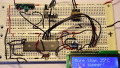
Receiver:

Give this project a try for yourself! Get the BOM.


The code helped me quite alot, had to change it a little bit since im using lm35 sensor. I only have one issue, for your code u send humidity and temp, i want to send temp, max and min temp. i tried using ur way with strcat but it only works with if im adding two arrays. hence i can only display temp and max or min. is there a way i could add 3 arrays using strcat. or is there another way. could you please make it simple, im a new to programming. Thank you
Is it possible to use a standard Arduino to program the standalone ATmega 328 chip for transmission, rather than using the MKII Programmer? Then simply remove the DIP package from the Arduino and swap in a different one and program that for the receiver?