 Facebook
 Google
 GitHub
 Linkedin
How to Use a Rotary Encoder in an MCU-Based Project
Learn how to use a rotary encoder in an Arduino project. Rotary encoders are electromechanical, electro-optical or electro-magnetic devices which convert rotational motion into digital or analog information.
Learn how to use an incremental rotary encoder in an Arduino project!
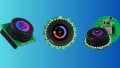
A rotary encoder is a electro-mechanical device which converts rotational motion into digital or analog information. It looks very much like a potentiometer but it can turn in either clockwise or counter-clockwise direction infinitely.There are several types of rotary encoders. Absolute and relative (incremental) encoders are the two main types.While an absolute encoder outputs a value proportional to the current shaft angle, an incremental encoder outputs the step of the shaft and its direction. Rotary encoders are becoming more and more popular in consumer eletronics especially as control knobs in addition to their many other application areas. They are taking the place of potentiometers and navigation buttons where fast navigation, adjustment, data entry, and selection are reqired. Some encoders also include a built-in pushbutton which generates additional input to the processor which can be used as another user command in the control loop. You can see a typical incremental rotary encoder with push-on button on the picture below.

In this article we will show you how to use an incremental rotary encoder in an Arduino project. We will explain how to deal with the contact noise and interpret the encoder signals in the MCU software by using interrupts.
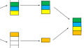
Incremental Encoder Quadrature Output Waveform
An incremental rotary encoder generates two output signals while its shaft is rotating which is also called quadrature ouptut. Depending on the direction, one of the signals leads the other. You can see the output signal waveforms of an incremental rotary encoder and the expected bit sequence below.

As you can see from the figure, both of the outputs stays HIGH at the initial state. When the encoder shaft starts to rotate in clockwise direction, Output A falls to LOW first and Output B follows it with a lag. In a counter-clockwise direction the operation turns opposite. Time intervals on the waveform depend on the rotation speed but the signal lagging is guaranteed in encoder operation. We will build the whole scenario on this characteristic of the incremental rotary encoder.
Filtering Out the Contact Noise of a Mechanical Encoder
Mechanical encoders have built-in switches which generate the quadrature waveform during rotation. Those switches generate noise during the closing and the opening moments of their contacts. In the figure below, you can see the actual behavior of an output signal.
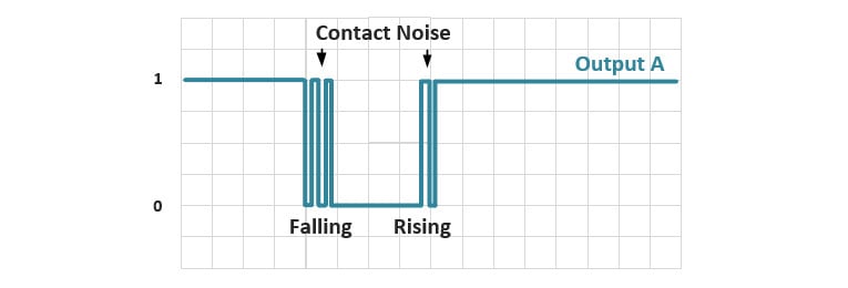
The contact noise is a major problem when dealing with the encoder signals. They cause erroneous direction and rotation detection and make using the encoders problematic. We can get rid of the contact noise by filtering it out in the software or by using some extra filtering circuits.
Filtering the noise out in the MCU software is one option but it has some disadvantages. You need to write a more complex code to handle the noise. Filtering will take processing time and put delays to your work flow. You may need to set timers to ignore the noisy intervals. At the end of the day, it is possible that you can’t get a satisfactory and robust result.
Filtering the noise out by using extra hardware is easier and it stops the noise at its source. What you need is a first order RC filter. You can see how the signal will look like after you use an RC filter.

RC filter slows down the fall time and the rise time and provides hardware de-bouncing. You should consider the maximum frequency of rotation while choosing the resistor and the capacitor pair. Otherwise the expected response of the encoder will also be filtered.
Sample Application
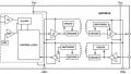
We are building an application to demonstrate how to use a rotary encoder in an Arduino project. We will use the encoder for navigation, data entry and selection. The circuit diagram of the application is given below.
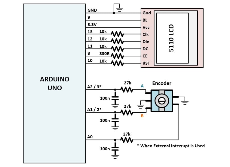
The circuit is built around Arduino Uno. A Nokia 5110 LCD is used for graphical interface. A mechanical rotary encoder with push-on switch and its RC filters are also included to be used as the controller.
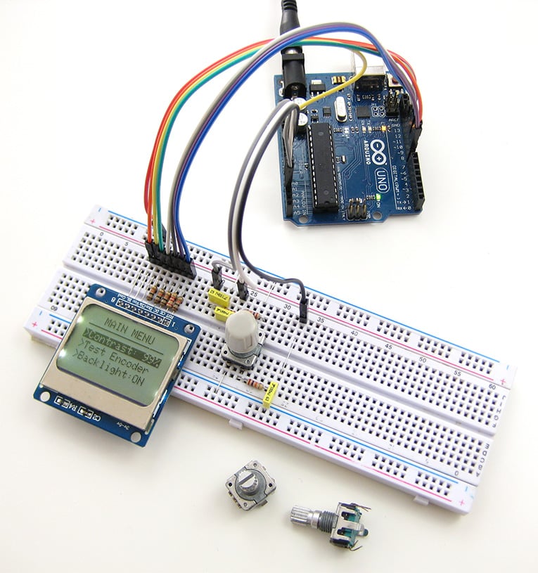
We will design a simple menu based software where the operation of rotary encoder is demonstrated.
Handling the Encoder Signals by Using Interrupts
Encoder signals should be detected and interpreted in the software as fast as possible not to block the main process flow. We can detect the signals by polling in the main loop or using interrupts. Polling is not an efficient way because you will need to reserve time and resource in your main loop which will bring extra delays. Using interrupts is a faster and cost effective solution. We will show you how to use interrupts to handle the encoder signals.
There are two types of interrupts in Atmega328 that can be used for this purpose; External Interrupt and Pin Change Interrupt. INT0 and INT1 pins are assigned to External Interrupt while PCINT0-PCIN15 are assigned to Pin Change Interrupt. External Interrupt can detect whether the input signal is falling or rising and can be triggered in one of the selected states which are: rising, falling or toggling. There are much more hardware resource for Pin Change Interrupt but it cannot detect the falling or the rising edge and it is triggered when any logical change (toggling) occurs.
To use the Pin Change Interrupt, connect the rotary A and B outputs to A1 and A2 pins and button output to A0 pins of Arduino as shown in the circuit diagram. Set A0, A1 and A2 pins as inputs and enable their internal pull-up resistors. Enable Pin Change Interrupt in PCICR register and enable interrupts for A0, A1 and A2 pins in PCMS1 register. When any logical change is detected at one of these inputs, PCINT1_vect ISR (Interrupt Service Routine) will be called.
Since Pin Change Interrupt is triggered for any logical change, we need to track both A and B signals and detect a rotation when an expected sequence is received. As it can be seen from the waveform diagram, a clockwise motion generates A = …0011… and B = …1001… When we record both of the signals in bytes seqA and seqB by shifting in the last reading from right, we can compare these values and determine a new rotational step.
You can see the part of the code including the initialization and Pin Change Interrupt service routine.
void setup() {
  pinMode(A0, INPUT);
  pinMode(A1, INPUT);
  pinMode(A2, INPUT);

  // Enable internal pull-up resistors
  digitalWrite(A0, HIGH);
  digitalWrite(A1, HIGH);
  digitalWrite(A2, HIGH);

  PCICR =  0b00000010; // 1. PCIE1: Pin Change Interrupt Enable 1
  PCMSK1 = 0b00000111; // Enable Pin Change Interrupt for A0, A1, A2
}

void loop() {

  // MAIN LOOP
}

ISR (PCINT1_vect) {

// If interrupt is triggered by the button
  if (!digitalRead(A0)) {

    button = true;}

// Else if interrupt is triggered by encoder signals
  else {

    // Read A and B signals
    boolean A_val = digitalRead(A1);
    boolean B_val = digitalRead(A2);

    // Record the A and B signals in seperate sequences
    seqA <<= 1;
    seqA |= A_val;

    seqB <<= 1;
    seqB |= B_val;

    // Mask the MSB four bits
    seqA &= 0b00001111;
    seqB &= 0b00001111;

    // Compare the recorded sequence with the expected sequence
    if (seqA == 0b00001001 && seqB == 0b00000011) {
      cnt1++;
      left = true;
      }

    if (seqA == 0b00000011 && seqB == 0b00001001) {
      cnt2++;
      right = true;
      }
  }

}
Using the External Interrupt makes the process simpler, but since there are only two pins assigned for this interrupt, you can’t use them for another purpose if you are using the encoder. To use External Interrupt, you should set 2 (INT0) and 3 (INT1) pins as inputs and enable their internal pull-up resistors. Then choose the falling edge trigger for both interrupts in EICRA register. Enable the External Interrupts in EIMSK register. When a new rotation begins, first the leading signal falls to LOW and the second one remains HIGH for a while. So we need to detect when the other signal stays high during an interrupt. After the leading signal falls, after some time the other signal will also fall to LOW which will create another interrupt. But this time the other signal (leading) will be LOW which means that this is not the start of a new rotation so we ignore it.
You can see the part of the code including the initialization and External Interrupt service routine.
void setup() {
  pinMode(2, INPUT);
  pinMode(3, INPUT);

  // Enable internal pull-up resistors
  digitalWrite(2, HIGH);
  digitalWrite(3, HIGH);

  EICRA = 0b00001010; // Select the falling edge trigger
  EIMSK = 0b00000011; // Enable External Interrupts
}

void loop() {

  // MAIN LOOP
}

ISR (INT0_vect) {

  // If the other signal is HIGH, this is a new rotation
  if (digitalRead(3) == HIGH) {
    left = true;
   }

}

ISR (INT1_vect) {

  // If the other signal is HIGH, this is a new rotation
  if (digitalRead(2) == HIGH) {
    right = true;
    }

}

The whole Arduino sketch including the main loop is given below:
#include
#include
#include

volatile byte seqA = 0;
volatile byte seqB = 0;
volatile byte cnt1 = 0;
volatile byte cnt2 = 0;
volatile boolean right = false;
volatile boolean left = false;
volatile boolean button = false;
boolean backlight = true;
byte menuitem = 1;
byte page = 1;

Adafruit_PCD8544 display = Adafruit_PCD8544(13, 12,11, 8, 10);

void setup() {

  pinMode(A0, INPUT);
  pinMode(A1, INPUT);
  pinMode(A2, INPUT);

  // Enable internal pull-up resistors
  digitalWrite(A0, HIGH);
  digitalWrite(A1, HIGH);
  digitalWrite(A2, HIGH);

  // Turn on LCD backlight
  pinMode(9, OUTPUT);
  digitalWrite(9, HIGH);

  PCICR =  0b00000010; // 1. PCIE1: Pin Change Interrupt Enable 1
  PCMSK1 = 0b00000111; // Enable Pin Change Interrupt for A0, A1, A2

  // Initialize LCD
  display.setRotation(2); // Set LDC orientation
  display.begin(60);      // Set LCD contrast
  display.clearDisplay(); // Clear display
  display.display();      // Apply changes

  sei();
}

void loop() {

  // Create Menu Pages
  if (page==1) {

    display.setTextSize(1);
    display.clearDisplay();
    display.setTextColor(BLACK, WHITE);
    display.setCursor(15, 0);
    display.print("MAIN MENU");
    display.drawFastHLine(0,10,83,BLACK);
    display.setCursor(0, 15);
    if (menuitem==1) { display.setTextColor(WHITE, BLACK);}
    else {display.setTextColor(BLACK, WHITE);}
    display.print(">Contrast: 99%");
    display.setCursor(0, 25);
    if (menuitem==2) { display.setTextColor(WHITE, BLACK);}
    else {display.setTextColor(BLACK, WHITE);}
    display.print(">Test Encoder");
    if (menuitem==3) { display.setTextColor(WHITE, BLACK);}
    else {display.setTextColor(BLACK, WHITE);}
    display.setCursor(0, 35);
    display.print(">Backlight:");
    if (backlight) {display.print("ON");}
    else {display.print("OFF");}
    display.display();}

  else if (page==2) {
    display.setTextSize(1);
    display.clearDisplay();
    display.setTextColor(BLACK, WHITE);
    display.setCursor(15, 0);
    display.print("ENC. TEST");
    display.drawFastHLine(0,10,83,BLACK);
    display.setCursor(5, 15);
    display.print("LEFT    RIGHT");
    display.setTextSize(2);
    display.setCursor(5, 25);
    display.print(cnt1);
    display.setCursor(55, 25);
    display.print(cnt2);
    display.setTextSize(2);
    display.display();
  }

  // Take action if a new command received from the encoder
  if (left) {
    left = false;
    menuitem--;
    if (menuitem==0) {menuitem=3;}
  }

  if (right) {
    right = false;
    menuitem++;
    if (menuitem==4) {menuitem=1;}
  }

  if (button) {
    button = false;

    if (page == 1 && menuitem==3) {
      digitalWrite(9, LOW);
      if (backlight) {backlight = false; digitalWrite(9, LOW);}
      else {backlight = true; digitalWrite(9, HIGH);}
      }

    else if (page == 1 && menuitem==2) {
      page=2;
      cnt1=0;
      cnt2=0;
     }

    else if (page == 2) {
      page=1;
     }
   }

  }


ISR (PCINT1_vect) {

// If interrupt is triggered by the button
  if (!digitalRead(A0)) {

    button = true;}

// Else if interrupt is triggered by encoder signals
  else {

    // Read A and B signals
    boolean A_val = digitalRead(A1);
    boolean B_val = digitalRead(A2);

    // Record the A and B signals in seperate sequences
    seqA <<= 1;
    seqA |= A_val;

    seqB <<= 1;
    seqB |= B_val;

    // Mask the MSB four bits
    seqA &= 0b00001111;
    seqB &= 0b00001111;

    // Compare the recorded sequence with the expected sequence
    if (seqA == 0b00001001 && seqB == 0b00000011) {
      cnt1++;
      left = true;
      }

    if (seqA == 0b00000011 && seqB == 0b00001001) {
      cnt2++;
      right = true;
      }
  }

}
You can see the encoder in action in the following video:
Give this project a try for yourself! Get the BOM.


HI
I build this and it works nice on the UNO, but on the MEGA 2560 i can’t get the rotary encoder to work at all, do you have any ideas?
GREATEST article covering ARDUINO & Rotary Encoders considering ATMega328 limited interrupts! I was thinking about complimentary circuit for 2x encoders, so to generate one interrupt for any signal change and I’d read the pins to determine the very event source. But this article discovered that there are more interrupts available in the Mega328, so I need no helping circuit anymore – just perfect! Exactly what I was dreaming to have found!