 Facebook
 Google
 GitHub
 Linkedin
How to Use RTC with Arduino and LCD
This article will show you one way of making an accurate clock by using the Real Time Clock IC DS1307. The time will be shown on a LCD display.
How to make an accurate clock using the Real Time Clock IC DS1307. The time will be shown on a LCD display.
Requirements
- Computer running Arduino 1.6.5
- Arduino
- Jumper wires
- Breadboard
- Parts from parts list
You can substitute the Arduino with another IC from ATMEL, but make sure it has the sufficient number of input and output pins along with I2C capability. I'm using the ATMega168A-PU. If you do that, you will need a programmer. I have the AVR MKII ISP programmer.
It is recommended that the reader is familiar with breadboarding, programming in the Arduino environment, and has some knowledge of the C programming language. The two programs below should not need additional explanation.
Introduction
How do microcontrollers keep track of time and date? The regular microcontroller has a timer function that starts at 0 (zero) when power is applied, and then it starts to count. In the Arduino world, we can use the millis() function to reset how many milliseconds have passed since the power was applied. When you disconnect and reconnect the power, it starts all over again. This is not so convenient when it comes to clocks and dates.
That is where the Real Time Clock--or the RTC--chip comes in handy. This IC, with a 3v coin cell battery or another 3v power supply, keeps track of the time and date. The clock/calendar provides seconds, minutes, hours, day, date, month, and year information. The IC corrects for months with 30/31 days and leap years. The communication is done with the I2C bus. The I2C bus will not be discussed here.
If the main circuit's Vcc falls below Vbat, the RTC switches automatically over to a low-power battery backup mode. The backup battery is usually a 3v coin cell battery connected to PIN 3 and GND. This way, the IC is still keeping track of time and date, and when power is applied to the main circuitry, the microcontroller gets the current time and date.
In this project we are using the DS1307. On this IC, PIN 7 is a SQW/OUT pin. You can use this pin to flash a LED, or to clock the microcontroller. We will do both. The following image, from the datasheet, helps us understand the SQW/OUT.

This table helps you with the frequency:
| Freq | BIT7 & BIT6 & BIT5 | BIT4 | BIT3 & BIT2 | BIT1 | BIT0 |
|---|---|---|---|---|---|
| 1Hz | 0 | 1 | 0 | 0 | 0 |
| 4.096Hz | 0 | 1 | 0 | 0 | 1 |
| 8.192Hz | 0 | 1 | 0 | 1 | 0 |
| 32.768Hz | 0 | 1 | 0 | 1 | 1 |
If you connect an LED and a resistor to PIN 7, and want it to flash with 1Hz frequency, you write 0b00010000 to the control register memory address. If you want 4.096 Hz, you would write 0b000100001. Now you would need an oscilloscope to see the pulses, since the LED is flashing so fast that it looks like it is constant on. We are using 1Hz.
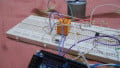
Hardware
Here's the block diagram for what we want.

We want:
- ISP (In System Programming) to program the microcontroller
- Push buttons to set the time and date
- The microcontroller to communicate with the RTC via I2C
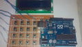
- Display the time and date on the LCD
The schematic diagram:

Click on image for full size.
Partlist
This is a screenshot from Eagle:

Software
We will be using two different sketches in this how-to: one that writes the time and date to the RTC, and one that reads the time and date from the RTC. I have done it like this so you will have a better overview of what is going on. We will be using the same circuit as above for both the programs.
First we will write the time and date to the RTC, which is like setting the time on a watch.
We are using two switches. One is to increase the hour, minute, date, month, year and day of week, and the other is to choose between them. The application does not read values from any critical sensors, so we are using interrupts to check if a switch is pressed and to handle the switch bounce. For more information on switch bounce read this.
The following code will set the values and write them to the RTC:
// Include header files
#include
#include
// LCD pin definitions
#define RS 9
#define E 10
#define D4 8
#define D5 7
#define D6 6
#define D7 5
LiquidCrystal lcd(RS, E, D4, D5, D6, D7);
// Interrupt 0 is hardware pin 4 (digital pin 2)
int btnSet = 0;
// Interrupt 1 is hardware pin 5 (digital pin 3)
int btnSel = 1;
// Interrupt state
int togBtnSet = false;
int togBtnSel = false;
// Time and date variables
int tmpHour = 0;
int tmpMinute = 0;
int tmpDate = 0;
int tmpMonth = 0;
int tmpYear = 0;
int tmpDay = 0;
int tmpSecond = 0;
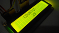
int counterVal = 0;
// Variable to keep track of where we are in the "menu"
int myMenu[6]; // 0=Hour, 1=Minutes, 2=date, 3=MOnth, 4=Year, 5=DOW
int menuCounter = 0;
// A array of the weekday
char* days[] = { "NA", "Mon", "Tue", "Wed", "Thu", "Fre", "Sat", "Sun" };
void setup() {
// Interrupt declaration, execute increaseValue/nextItem function
// when btnXXX is RISING
attachInterrupt(btnSet, increaseValue, RISING);
attachInterrupt(btnSel, nextItem, RISING);
Wire.begin();
lcd.begin(16,2);
showWelcome();
}
// Interrupt function
void increaseValue()
{
// Variables
static unsigned long lastInterruptTime = 0;
// Making a timestamp
unsigned long interruptTime = millis();
// If timestamp - lastInterruptTime is greater than 200
if (interruptTime - lastInterruptTime > 200)
{
// Toggle the variable
togBtnSet = !togBtnSet;
// Increase the counterVal by 1
counterVal++;
}
// Setting lastInterruptTime equal to the timestamp
// so we know we moved on
lastInterruptTime = interruptTime;
}
// Next menuItem Interrupt function
void nextItem()
{
static unsigned long lastInterruptTime = 0;
unsigned long interruptTime = millis();
if (interruptTime - lastInterruptTime > 200)
{
togBtnSel = !togBtnSel;
// Increase the menu counter so we move to next item
menuCounter++;
// Placing the counterVal in the menucounters array position
myMenu[menuCounter] = counterVal;
// Reset counterVal, now we start at 0 on the next menuItem
counterVal = 0;
}
lastInterruptTime = interruptTime;
}
// Function that convert decimal numbers to binary
byte decToBCD(byte val)
{
return ((val/10*16) + (val));
}
// Short welcome message, now we know everything is OK
void showWelcome()
{
lcd.setCursor(2,0);
lcd.print("Hello world.");
lcd.setCursor(3,1);
lcd.print("I'm alive.");
delay(500);
lcd.clear();
}
// Funcion to set the hour
void setHour()
{
lcd.setCursor(0,0);
lcd.print("Set hour. ");
// Checks if interrupt has occured = button pressed
if (togBtnSet)
{
// Update array value with counterVal
myMenu[menuCounter] = counterVal;
lcd.setCursor(7,1);
// Print the new value
lcd.print(myMenu[menuCounter]); lcd.print(" ");
}
else
{
// Update array value with counterVal
myMenu[menuCounter] = counterVal;
lcd.setCursor(7,1);
// Print the new value
lcd.print(myMenu[menuCounter]); lcd.print(" ");
}
}
// Function to set minutes
void setMinute()
{
lcd.setCursor(0,0);
lcd.print("Set minute. ");
if (togBtnSet)
{
myMenu[menuCounter] = counterVal;
lcd.setCursor(7,1);
lcd.print(myMenu[menuCounter]); lcd.print(" ");
}
else
{
myMenu[menuCounter] = counterVal;
lcd.setCursor(7,1);
lcd.print(myMenu[menuCounter]); lcd.print(" ");
}
}
// Function to set date
void setDate()
{
lcd.setCursor(0,0);
lcd.print("Set date. ");
if (togBtnSet)
{
myMenu[menuCounter] = counterVal;
lcd.setCursor(7,1);
lcd.print(myMenu[menuCounter]); lcd.print(" ");
}
else
{
myMenu[menuCounter] = counterVal;
lcd.setCursor(7,1);
lcd.print(myMenu[menuCounter]); lcd.print(" ");
}
}
// Function to set month
void setMonth()
{
lcd.setCursor(0,0);
lcd.print("Set month. ");
if (togBtnSet)
{
myMenu[menuCounter] = counterVal;
lcd.setCursor(7,1);
lcd.print(myMenu[menuCounter]); lcd.print(" ");
}
else
{
myMenu[menuCounter] = counterVal;
lcd.setCursor(7,1);
lcd.print(myMenu[menuCounter]); lcd.print(" ");
}
}
// Function to set year
void setYear()
{
lcd.setCursor(0,0);
lcd.print("Set year. ");
if (togBtnSet)
{
myMenu[menuCounter] = counterVal;
lcd.setCursor(7,1);
lcd.print(myMenu[menuCounter]); lcd.print(" ");
}
else
{
myMenu[menuCounter] = counterVal;
lcd.setCursor(7,1);
lcd.print(myMenu[menuCounter]); lcd.print(" ");
}
}
// Function to set the day of week
void setDOW()
{
lcd.setCursor(0,0);
lcd.print("Set day (1=mon).");
if (togBtnSet)
{
myMenu[menuCounter] = counterVal;
lcd.setCursor(7,1);
lcd.print(myMenu[menuCounter]); lcd.print(" ");
}
else
{
myMenu[menuCounter] = counterVal;
lcd.setCursor(7,1);
lcd.print(myMenu[menuCounter]); lcd.print(" ");
}
}
// Write the data to the RTC
void writeRTC()
{
Wire.beginTransmission(0x68);
Wire.write(0); // Start address
Wire.write(0x00); // seconds
Wire.write(decToBCD(myMenu[1])); // convert tmpMinutes to BCD and write them
Wire.write(decToBCD(myMenu[0])); // convert tmpHour to BCD and write them
Wire.write(decToBCD(myMenu[5])); // convert tmpDay to BCD and write them
Wire.write(decToBCD(myMenu[2])); // convert tmpDate to BCD and write them
Wire.write(decToBCD(myMenu[3])); // convert tmpMonth to BCD and write them
Wire.write(decToBCD(myMenu[4])); // convert tmpYear to BCD and write them
Wire.write(0b00010000); // enable 1Hz Square wave on PIN7
Wire.endTransmission(); // close the transmission
}
// Show the time
// You need to use the other program to see the RTC is working
void showTime()
{
lcd.setCursor(0,0);
lcd.print(" ");
lcd.print(myMenu[0]); lcd.print(":"); // hour
lcd.print(myMenu[1]); lcd.print(":"); lcd.print("00 "); // minute
lcd.setCursor(3,1);
lcd.print(days[myMenu[5]]); lcd.print(" "); // DOW
lcd.print(myMenu[2]); lcd.print("."); // date
lcd.print(myMenu[3]); lcd.print("."); // month
lcd.print(myMenu[4]); lcd.print(" "); // year
// Call the writeRTC function
writeRTC();
}
void loop()
{
if (menuCounter == 0)
{
setHour();
}
if (menuCounter == 1)
{
setMinute();
}
if (menuCounter == 2)
{
setDate();
}
if (menuCounter == 3)
{
setMonth();
}
if (menuCounter == 4)
{
setYear();
}
if (menuCounter == 5)
{
setDOW();
}
if (menuCounter == 6)
{
showTime();
}
}
The program starts with a short welcome message. This message tells you that power is applied, LCD is working, and that the program has started to run.
To read from the RTC and show the time and date, you will have to program your microcontroller with the following program. The program reads the time and date values from the RTC and displays them on the LCD.
// Include header files
#include
#include

// LCD pin definitions
#define RS 9
#define E 10
#define D4 8
#define D5 7
#define D6 6
#define D7 5

LiquidCrystal lcd(RS, E, D4, D5, D6, D7);

// Pin that will receive clock pulse from RTC
int clockPin = 0;

// Time and date vaiables
byte second;
byte minute;
byte hour;
byte day;
byte date;
byte month;
byte year;

// A array of the weekday
char* days[] = { "NA", "Mon", "Tue", "Wed", "Thu", "Fre", "Sat", "Sun" };

// Function run once
void setup() {
  pinMode(clockPin, INPUT); pinMode(clockPin, LOW);
  Wire.begin();
  lcd.begin(16,2);
  showWelcome();
}

// Nice welcome message, then we know LCD is OK
void showWelcome()
{
  lcd.setCursor(2,0);
  lcd.print("Hello world.");
  lcd.setCursor(3,1);
  lcd.print("I'm alive.");
  delay(500);
  lcd.clear();
}

// Doing this forever
void loop() {
  // While clockPin is high
  while (digitalRead(clockPin))
  {
    // start the I2C transmission, at address 0x68
    Wire.beginTransmission(0x68);

    // Start at address 0
    Wire.write(0);

    // Close transmission
    Wire.endTransmission();

    // Start to read the 7 binary data from 0x68
    Wire.requestFrom(0x68, 7);
    second = Wire.read();
    minute = Wire.read();
    hour = Wire.read();
    day = Wire.read();
    date = Wire.read();
    month = Wire.read();
    year = Wire.read();

    // Formatting and displaying time
    lcd.setCursor(4,0);
      if (hour < 10) lcd.print("0");
        lcd.print(hour, HEX); lcd.print(":");
      if (minute < 10) lcd.print("0");
        lcd.print(minute, HEX); lcd.print(":");
      if (second < 10) lcd.print("0");
        lcd.print(second, HEX);
    lcd.setCursor(2,1);

    // Formatting and displaying date
    lcd.print(days[day]); lcd.print(" ");
      if (date < 10) lcd.print("0");
        lcd.print(date, HEX); lcd.print(".");
      if (month < 10) lcd.print("0");
        lcd.print(month, HEX); lcd.print(".");
        lcd.print(year, HEX);
    } // end while
}
Conclusion
In this article, we've looked at the small DS1307 RTC IC from Maxim Integrated. We made one program that sets the time and date, and we made another program to read the time and date. To check if a switch was pressed, we used interrupts. The interrupts also took care of the switch bouncing.
Pictures & Video

Click on image for full size.

Click on image for full size.
Setting the time
Reading the time
Give this project a try for yourself! Get the BOM.


Hello
Just had a quick look, very nicely done and could be just what I’m looking to do.
I’ll admit that I don’t have the hours in the day to ever learn Arduino usage properly, but I do like to get useful things working.
One project I have on the go is to update an RTC (I’ve tried most of them and yet to find one that keeps true second a month accuracy).
My approach has been to hack a radio controlled digital clock (MSF in my case) and use the alarm output to send out a wireless synchronising pulse, say, at midnight.
Most RTC chips will only lose or gain seconds a day at worst, so the idea would be to use the sync pulse to set the seconds and possibly the minutes back or forwards to 00:00.
A quick look at your article gives the idea of using your SET functions to do just that.
The long term aim is to get rid of the plethora of programmable timers etc. in the house, none of which keep good time and do my own, based around an accurate time source.
What do you think?
Just joined the site, at first look seems very useful, helpful and civilised.
hi, Please tell me if i upload these 2 codes to a 328 not connected to the circuit then later add the controller how can i get it to work, I get to set all but cant start running the clock. Its really no good to have to assemble all and then load sketches if lets say want to build a few clocks.