 Facebook
 Google
 GitHub
 Linkedin
Intro to Project Development with the Atmel SAM4S Xplained Pro
Learn about basic procedures and techniques for creating your own projects with Atmel’s SAM4S Xplained Pro development platform.
Learn about basic procedures and techniques for creating your own projects with Atmel’s SAM4S Xplained Pro development platform.
Required Hardware/Software
- SAM4S Xplained Pro starter kit, or the SAM4S Xplained Pro evaluation Kit plus the OLED1 Xplained Pro extension board
- Atmel Studio
Development Board vs. Custom Board
There is a vast chasm that separates buying a development kit from designing and assembling your own PCB. With the former, you simply place an order and a few days later you have an expertly designed, thoroughly tested, professionally assembled unit ready for your latest application. With the latter, you have hours of careful schematic design and PCB layout followed by expensive or labor-intensive PCB assembly, and of course there is always the looming possibility that the finished board will be partially or even primarily nonfunctional. Nevertheless, I like designing my own PCBs, one reason being that I can incorporate a wider variety of features. It follows that I would be especially pleased with a development board that provides the usual advantages while offering a less restricted array of capabilities that can be conveniently evaluated. If you feel the same way, I think that you’ll like Atmel’s Xplained Pro platform.
The Starter Kit
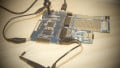
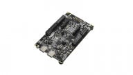
In this project we will use the SAM4S Xplained Pro board. The processor board (aka “evaluation kit”) itself is not so impressive; the impressive part is the numerous Xplained Pro extension (aka “add-on”) modules that you can plug in to one of the extension connectors on the processor board. You can go here for a list of Xplained Pro evaluation kits and extension modules. If you buy the SAM4S Xplained Pro starter kit, you get a development board for the ATSAM4SD32C microcontroller along with three extension modules: one with an OLED display along with some LEDs and pushbuttons; one with (among other things) a light sensor, a temperature sensor, a low-pass filter, and a microSD card connector loaded with a 2 GB microSD card (this module is referred to as the “I/O board”); and one with a fairly-generously-sized through-hole prototyping area accompanied by a conveniently labeled signal header.

This project requires only the OLED extension module, though the labeled header on the prototyping module is handy if you want to probe a signal.
The A – S – F
For people like me who began their professional career by programming an 8051 using something called assembly language, the Atmel Software Framework (ASF) is an overwhelmingly extensive software library that makes microcontroller project development seem almost absurdly easy. However, all this prepackaged, über-abstracted firmware has pitfalls and difficulties of its own, so approach with caution. Furthermore, you’ve probably noticed that engineering never really gets easier, because system requirements develop in proportion to the sophistication and efficiency of our tools. Sure, once upon a time I had to use a little assembly code, but back then nobody expected to watch YouTube videos on a wristwatch.
So anyways, an essential step in developing projects with Atmel devices is becoming acquainted with the ASF. By the end of this article you should have a decent understanding of what the ASF is and how to use it; for now I’ll just a mention a few important points:
- ASF functionality covers not only the microcontrollers themselves but also development boards and external third-party devices, such as the OLED display on the OLED board and the temperature sensor on the I/O board (as well as a long list of others not included in this starter kit—Ethernet transceiver, LCD display, 640 × 480 CMOS image sensor, pyroelectric infrared sensor. . . .)
- The ASF is integrated (quite smoothly, I would say) into Atmel Studio (which you can download for free). So incorporating ASF functionality into your project does not require an additional download or a separate program—ASF configuration, code development, compiling, and debugging all take place in Atmel Studio.
- To quote Atmel: “The intention of ASF is to provide a rich set of proven drivers and code modules developed by Atmel experts to reduce customer design-time.” “ASF is . . . designed to be used for evaluation, prototyping, design, and production phases.” The point here is that Atmel considers the ASF to be pretty solid—something you can rely on during the prototyping stage and confidently include even in production code.
Step by Step
Without further ado, let’s carefully go through the process of creating a new SAM4S Xplained Pro application. The goal here is a simple “video game” that utilizes two components on the OLED extension board, namely, the OLED display and pushbutton 2. We’ll cover the initial procedure in this article and then develop the rest of the functionality in Part 2.
- Open Atmel Studio.
- Attach the OLED extension board to the EXT3 header on the SAM4S board, then connect a USB cable from the “DEBUG USB” connector on the SAM4S board to one of the PC’s USB ports. You will see the following screen when Atmel Studio recognizes the evaluation kit.

- Go to File → New → Project.
- Select “GCC C ASF Board Project.”

- Type the name of the project and click OK.

- Choose “Select By Board” and scroll down to “SAM4S Xplained Pro - ATSAM4SD32C.” As indicated by the dark-gray rectangle in the scroll bar, it’s a little past halfway down. Click OK.

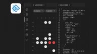
- When Atmel Studio finishes creating the project, look on the far right and you will see the new project listed in the “Solution Explorer” pane.
- The next image shows the folders and files included in the “src” directory. You will notice that most of the files have a dark-gray square in the lower-right-hand corner. This indicates that the file has not yet been modified. After you modify the file, the square turns red.

- Take a look at the “main.c” file. It already has some informational comments and a bare-minimum code framework to get you started. You can go ahead and delete everything in the main() function.
- Now go to Project → ASF Wizard. In the top left, select the new project (in this case OLEDTargetPractice). The “Select Modules” pane shows you which ASF modules are already included in the project. These are the modules that Atmel Studio included by default. Since we will be using the OLED display, we need to add the ASF module for the OLED interface.

- Scroll down and select the “SSD1306 OLED controller (component)” module. At the bottom of the window, click “Add >>” then “Apply”; a dialog will pop up giving you the “summary of operations for selected options.” Click OK. Atmel Studio automatically modifies the project files to ensure that this ASF module is properly incorporated into the project. We don’t need to add any more modules for this project, so you can close the “ASF Wizard” window.

Finally, We’re Ready to Write Some Code
The following code excerpt shows the main() function for this portion of the project. Copy and paste so that your main() function is the same as mine. Refer to the comments in the code for details.
int main (void)
{
	char DisplayString[] = "This is an OLED test.";
	char DisplayChar[2];
	uint8_t DisplayString_Length = 21;
	uint8_t n;

	//clock configuration and initialization
	sysclk_init();

	/*Disable the watchdog timer and configure/initialize
	port pins connected to various components incorporated
	into the SAM4S Xplained development platform, e.g., the
	NAND flash, the OLED interface, the LEDs, the SW0 pushbutton.*/
	board_init();

	//initialize SPI and the OLED controller
	ssd1306_init();

	/*The second character in this two-character array must be zero
	so that the ssd1306_write_text() function correctly interprets the
	array as a one-character string.*/
	DisplayChar[1] = 0;

	while (1)
	{
		/*Clear the OLED screen, then set the cursor to the
                top-left character position.*/
		ssd1306_clear();
		ssd1306_set_page_address(0);
		ssd1306_set_column_address(0);

		for (n = 0; n < DisplayString_Length; n++)
		{
			/*Copy the current character of DisplayString
			to the one-character array DisplayChar.*/
			DisplayChar[0] = DisplayString[n];

			//display the single character
			ssd1306_write_text(DisplayChar);

			//the ASF includes handy delay functions
			delay_ms(400);
		}
	}
}
What About Hardware Configuration?
The ASF framework generates config files that you can conveniently modify according to your application requirements.

ASF functions look at the information in these files to determine how exactly to configure the hardware. For example, the “conf_clock.h” file includes a list of preprocessor definitions related to the system clock source, the system clock prescaler, and the PLL (phase-locked loop) settings. You “configure” this clock hardware by commenting/uncommenting certain preprocessor definitions or by modifying the definitions. Then, all you have to do is call the sysclk_init() function, which will kindly incorporate your preferences as it takes care of all the clock-configuration details.
Let’s go ahead and modify the configuration files, and after that we will actually be able to display text on the OLED.
- In “conf_board.h”: Add the “Enable the OLED screen” definitions.
#ifndef CONF_BOARD_H
#define CONF_BOARD_H

// Enable the OLED screen
#define CONF_BOARD_SPI
#define CONF_BOARD_SPI_NPCS1
#define CONF_BOARD_SPI_NPCS2
#define CONF_BOARD_OLED_UG_2832HSWEG04

#endif /* CONF_BOARD_H */
- In “conf_clock.h”: Comment out the “PLL1 (B)” definitions and the “USB Clock Source” definitions. This project doesn’t use PLL1 or USB.
#ifndef CONF_CLOCK_H_INCLUDED
#define CONF_CLOCK_H_INCLUDED

// ===== System Clock (MCK) Source Options
//#define CONFIG_SYSCLK_SOURCE        SYSCLK_SRC_SLCK_RC
//#define CONFIG_SYSCLK_SOURCE        SYSCLK_SRC_SLCK_XTAL
//#define CONFIG_SYSCLK_SOURCE        SYSCLK_SRC_SLCK_BYPASS
//#define CONFIG_SYSCLK_SOURCE        SYSCLK_SRC_MAINCK_4M_RC
//#define CONFIG_SYSCLK_SOURCE        SYSCLK_SRC_MAINCK_8M_RC
//#define CONFIG_SYSCLK_SOURCE        SYSCLK_SRC_MAINCK_12M_RC
//#define CONFIG_SYSCLK_SOURCE        SYSCLK_SRC_MAINCK_XTAL
//#define CONFIG_SYSCLK_SOURCE        SYSCLK_SRC_MAINCK_BYPASS
#define CONFIG_SYSCLK_SOURCE        SYSCLK_SRC_PLLACK
//#define CONFIG_SYSCLK_SOURCE        SYSCLK_SRC_PLLBCK

// ===== System Clock (MCK) Prescaler Options   (Fmck = Fsys / (SYSCLK_PRES))
//#define CONFIG_SYSCLK_PRES          SYSCLK_PRES_1
#define CONFIG_SYSCLK_PRES          SYSCLK_PRES_2
//#define CONFIG_SYSCLK_PRES          SYSCLK_PRES_4
//#define CONFIG_SYSCLK_PRES          SYSCLK_PRES_8
//#define CONFIG_SYSCLK_PRES          SYSCLK_PRES_16
//#define CONFIG_SYSCLK_PRES          SYSCLK_PRES_32
//#define CONFIG_SYSCLK_PRES          SYSCLK_PRES_64
//#define CONFIG_SYSCLK_PRES          SYSCLK_PRES_3

// ===== PLL0 (A) Options   (Fpll = (Fclk * PLL_mul) / PLL_div)
// Use mul and div effective values here.
#define CONFIG_PLL0_SOURCE          PLL_SRC_MAINCK_XTAL
#define CONFIG_PLL0_MUL             20
#define CONFIG_PLL0_DIV             1

// ===== PLL1 (B) Options   (Fpll = (Fclk * PLL_mul) / PLL_div)
// Use mul and div effective values here.
//#define CONFIG_PLL1_SOURCE          PLL_SRC_MAINCK_XTAL
//#define CONFIG_PLL1_MUL             16
//#define CONFIG_PLL1_DIV             2

// ===== USB Clock Source Options   (Fusb = FpllX / USB_div)
// Use div effective value here.
//#define CONFIG_USBCLK_SOURCE        USBCLK_SRC_PLL0
//#define CONFIG_USBCLK_SOURCE        USBCLK_SRC_PLL1
//#define CONFIG_USBCLK_DIV           2
- In “conf_spi_master.h”: No changes required.
- In “conf_ssd1306.h”: Delete everything under the “Support and FAQ . . .” comment and instead use the following, which is taken from Atmel’s example code:
/*
 * Support and FAQ: visit Atmel Support
 */

#ifndef CONF_SSD1306_H_INCLUDED
#define CONF_SSD1306_H_INCLUDED

// Interface configuration for SAM4S Xplained Pro
#define SSD1306_SPI_INTERFACE
#define SSD1306_SPI SPI

#define SSD1306_DC_PIN       UG_2832HSWEG04_DATA_CMD_GPIO
#define SSD1306_RES_PIN      UG_2832HSWEG04_RESET_GPIO
#define SSD1306_CS_PIN       UG_2832HSWEG04_SS

/* Minimum clock period is 50ns@3.3V -> max frequency is 20MHz */
#define SSD1306_CLOCK_SPEED          UG_2832HSWEG04_BAUDRATE
#define SSD1306_DISPLAY_CONTRAST_MAX 40
#define SSD1306_DISPLAY_CONTRAST_MIN 30

#endif /* CONF_SSD1306_H_INCLUDED */
You can use the following link to download all the files associated with this project.
At this point we are ready to execute our thoroughly exhilarating text-display program. Click the “Start Without Debugging” button (i.e., the non-filled green triangle next to the filled green triangle), and if all goes well the functionality will be the same as what you see in the video at the end of this article.
Conclusion
Now you are familiar with the basic steps required for creating your own project with Atmel Studio, rather than more-or-less blindly modifying one of the example projects. In the next article we’ll finish our highly primitive video game, and in the process ,we’ll learn about interfacing with the display module and pushbuttons on the OLED extension board.
Next Article in Series: How to Create a Gaming System with the Atmel SAM4S Xplained Pro
Give this project a try for yourself! Get the BOM.


Thanks so much for putting this together! I also found a hands on course here
https://www.udemy.com/armcortex-adc
that helped me get started with using the ADC on SAM4s Xplained and reading the temperature sensor. Thanks for sharing!