Learn to Build a Photoelectric Sensor System Using an Arduino Uno and OpenPLC
Since photoelectric sensing can be achieved with electrical, electromechanical, and electronic components, learn to build, test, and implement a prototype photoelectric switch using off-the-shelf components with Arduino OpenPLC.
A vital component used in the control industry (and others, of course) is the electronic sensor. The electronic sensor’s importance in manufacturing is the ability to obtain performance data from various mechatronics-based automation systems. Mechatronics is a multi-interdisciplinary field that combines mechanical systems with electrical systems that include digital controls, electronic sensors, and control software.
A typical approach to managing mechatronics is to use a computerized-based controller capable of monitoring industrial processes and controlling electromechanical actuators. The PLC (programmable logic controller) is a computerized industrial controller capable of performing such industrial-related tasks. With an electronic sensor, the PLC can monitor various manufacturing processes and assist in improving electromechanical actuator performance.
With that background information in mind, this project will explore creating a specific electronic sensor, the photoelectric switch (also known as a photoelectric sensor), and using it with the Arduino OpenPLC platform.
Setting the Scene: What is a Phototransistor?
A phototransistor is a semiconductor component that detects and converts light into an electrical signal and is designed to respond to light instead of an input voltage. Like a typical transistor, a phototransistor is comprised of base, collector, and emitter layers. The layer that is light-sensitive is the base-collector junction. When light falls on the base-collector junction, a flow of electrons is created, allowing current amplification within the transistor. Phototransistors are packaged as two lead or thread lead components, which can be seen in Figure 1.

Figure 1. Phototransistor packages. Images [modified] used courtesy of Digi-Key's article and product page
Additionally, the electronic symbol for the phototransistor is shown in Figure 2.

Figure 2. The phototransistor’s electronic symbol.
With the base-collector junction being the sensitive layer, the two-pin component consisting of the collector and emitter leads is the commonly manufactured semiconductor part sold through electronic parts distributors. The phototransistor is typically configured as an NPN device using the base-collector junction as an internal light-sensing element. When light is present, the base-collector junction allows the base-emitter junction to conduct, thus turning the device into an optoelectrical switch. Another term used to describe the presence of light is photoemissivity, which is when a phototransistor’s base collector is in the presence of light, and the emission of electrons turns on this radiance solid-state component.
Like a limit switch, the phototransistor’s optoelectrical switching function can detect objects without physical contact. Unlike the limit switch, the phototransistor’s optoelectrical switching has no moving parts. Therefore, the phototransistor has a longer operating lifespan for switching than the limit switch. Overall, the phototransistor's longer operating lifespan is based on no mechanical contact wear like the typical limit switch.
Figure 3 shows the internal structure of a typical phototransistor.

Figure 3. Typical structure of a phototransistor. Image [modified] used courtesy of The Engineering Knowledge
With an understanding of the phototransistor, we will build a photoelectric switch to interact with our conceptual Arduino PLC using an OpenPLC ladder diagram (LD).
Photoelectric Sensor Basics—Reflective, Thru Beam, and Retroreflective
A photoelectric switch (or sensor) is an electronic device that can detect the absence or presence of an object using light and uses photo-emissive devices like photodiodes or phototransistors to detect light. The photoelectric switch has various light detection methods to detect the absence or presence of light, including:
- Reflective
- Thru beam
- Retroreflective
The reflective method, shown in Figure 4, uses one housing to package the light transmitter and light receiver. With this method, the light receiver has a photodiode or phototransistor to detect light emitted from a laser or LED (light-emitting diode). The light emitted by an LED or laser is reflected off the object (target) and detected by the phototransistor or photodiode.

Figure 4. Reflective model. Image used courtesy of Keyence
The thru beam approach (Figure 5) separates the transmitter and receiver components, where placing a target between the transmitter and receiver interrupts the light.

Figure 5. Thru beam method of target detection. Image used courtesy of Keyence
The final approach to using a photoelectric switch for object detection is retroreflective. Like the reflective model, the light emitter and receiver are packaged in one unit. The light emitted from the emitter hits a reflector and returns to the integrated light receiver. The presence of a target interrupts the emitted light. Figure 6 illustrates the retroreflective model of target detection using a photoelectric switch.

Figure 6. Retroreflective approach to target detection. Image used courtesy of Keyence
In this project, we will be building a photoelectric switch prototype based upon thru beam detection.
Photoelectric Sensor Wiring Diagrams and BOM
Finally, let's get into the hands-on information for this project! This photoelectric switch build consists of using off-the-shelf components. Here are the electrical, electromechanical, and electronic components you will use to build the photoelectric switch.
Parts Lists:
- FPT1 silicon NPN transistor – NTE30051 (Digi-Key part number: 2368-NTE30051-ND)
- Q1 2N3904 NPN transistor
- K1 5 VDC electromechanical relay – Omron G5Q-14-DC5 (Mouser Electronics part number: 653-G5Q -14-DC5)
- R1, R3 10 KΩ, 1/8 W, resistors
- R2 220 Ω, 1/8 W, resistor
- D1 1N4001 general-purpose silicon diode
Additionally, you will need the following components to wire the reset switch and blinking LED circuits.
- PB1 tactile pushbutton switch
- R4 10 KΩ, 1/8 W, resistor
- LED1 blinking red LED: EDGELEC, 5 mm (Amazon purchase link)
- R5 220 Ω, 1/8 W, resistor
With the components available, you will place them on the solderless breadboard. You can use Figure 7 to guide you.
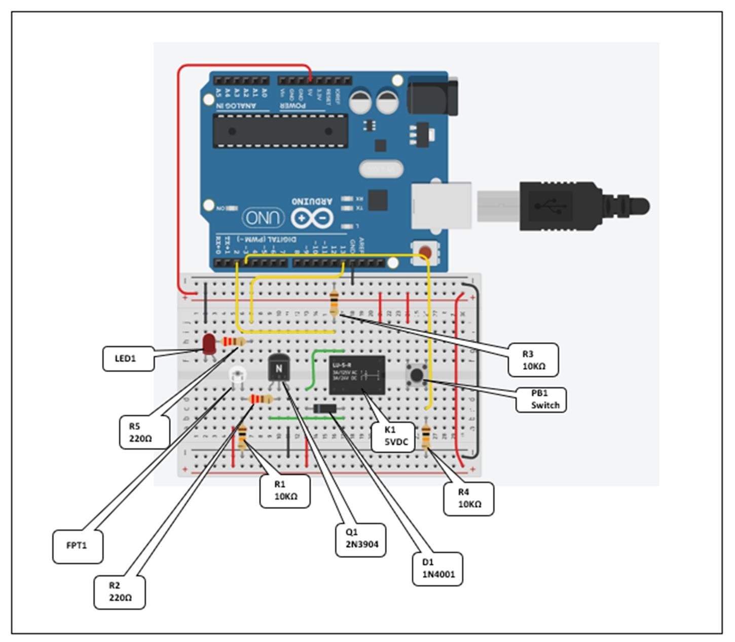
Figure 7. Electronic component placement onto a solderless breadboard [click image to enlarge].
Some electronic components are polarity sensitive; therefore, proper orientation onto the solderless breadboard is important. The electronic components that are polarity sensitive are FPT1, D1, Q1, and LED1.
The phototransistor (FPT1) collector pin is long; therefore, it will need to be wired to the +5V rail of the solderless breadboard. Wiring the phototransistor collector pin to the +5 V rail will ensure proper switching operation of the component. As an additional reference, Figure 8 shows the assembled and wired photoelectric switch on the solderless breadboard.
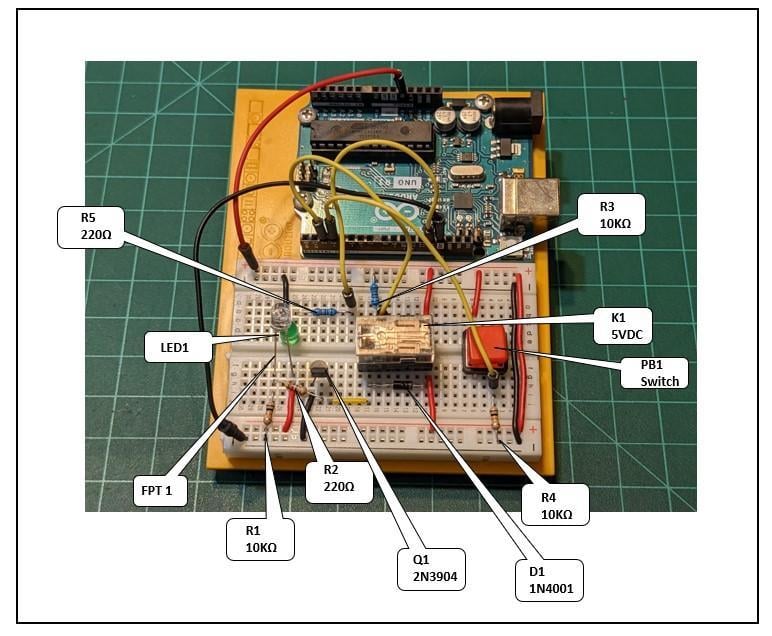
Figure 8. The completed photoelectric switch circuit [click image to enlarge].
Testing the Photoelectric Sensor
You can test the switching operation of the photoelectric switch using a digital multimeter (DMM). The DMM will measure the control switching voltage of the phototransistor, which is lightly placed over the device. Here are the measurement setup steps to test the photoelectric switch operation:
- Place a small black tube over the light sensing device to ensure that switching of the phototransistor properly occurs.
- Insert one end into the solderless breadboard ground rail with a jumper wire. A black or green wire will be the appropriate color for identifying ground.
- Take a red jumper wire and insert one end into the solderless breadboard cavity that electrically connects resistors R1 and R2 together.
- Take the other end of the black or green jumper wire and attach it to the DMM BLACK test lead.
- Take the other end of the red jumper wire and attach it to the DMM RED test lead.
- Attach the Arduino Uno board to an available USB port on your desktop personal computer (PC) or laptop computer.
- Place a flashlight over the small black tube; the DMM shall read a voltage of 1.20 VDC or greater.
- If the voltage reading is not 1.20 VDC or greater, check your wiring and perform step 8.
Figure 9 shows a TinkerCAD circuit model test setup.

Figure 9. TinkerCAD circuit model measurement test setup [click image to enlarge].
Figure 10 shows the actual measurement test set up with voltage readings from the phototransistor.

Figure 10. Actual measurement test setup.
Congratulations, you have built a photoelectric switch prototype using off-the-shelf components! The project’s final step is to wire and test the photoelectric switch with an Arduino Uno-based OpenPLC platform.
Arduino OpenPLC and the Photoelectric Sensor Controller
With the photoelectric switch operating properly, the final step in this project is wiring the light detection circuit to the Arduino-based OpenPLC platform. The concept of the photoelectric switch controller consists of wiring the photoelectric switch and a reset pushbutton to the Arduino Uno. The integration of these circuits forms the photoelectric switch controller concept. A blinking LED will provide an output response status of the photoelectric switch controller, properly detecting a light source. Figure 11 shows the systems block diagram of the photoelectric switch controller.

Figure 11. Photoelectric switch controller system block diagram.
The electrical wiring of the photoelectric switch, the reset pushbutton switch, and the blinking LED are captured on the electronic circuit schematic diagram shown in Figure 12.

Figure 12. The photoelectric switch controller electronic circuit schematic diagram [click image to enlarge].
The electronic circuit schematic diagram includes these circuit devices' input/output (I/O) wiring. You may reference Figure 8 for the final build of the photoelectric switch controller prototype.
The I/O circuit names, shown in Figure 13, are used to create the OpenPLC tags and the Ladder Diagram.
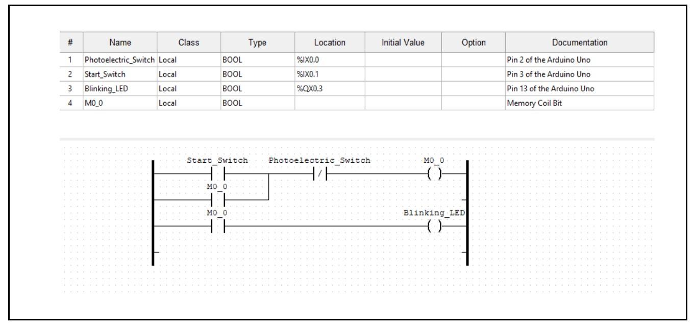
Figure 13. Start-reset Ladder Diagram and I/O tag list [click image to enlarge].
Figure 13 also shows the I/O tags for the OpenPLC start-reset LD. The LD shows that the photoelectric switch will perform the reset function. In an industrial control environment, a manual reset pushbutton switch will be wired as a contingency for the photoelectric switch failing in the system. The educational purpose of this conceptual controller is to show the effectiveness of the photoelectric switch in a control’s application. Pressing the "start" pushbutton switch will latch the blinking LED on. Placing a flashlight over the phototransistor will unlatch the control circuit, thereby turning off the blinking LED.
You can watch the video clip that demonstrates the photoelectric switch controller prototype in action here, or you can watch it down below.
Interactive Quiz:
In reviewing the start-reset LD, what output response of the Arduino-OpenPLC controller will be observed if the Photoelectric_Switch XIO (Examine If Open) bit instruction was changed to XIC (Examine If Closed)?
Let us know your answer in the comments down below!