 Facebook
 Google
 GitHub
 Linkedin
NES Controller Interface with an Arduino UNO
Learn about the NES Controller's data protocol, then use this knowledge to easily integrate into an Arduino Uno.
The Nintendo Entertainment System, also known as the NES console, was once the king of all video game systems.

It's time to take over the world.
Nowadays, these are pretty antiquated and only the most nostalgic of gamers will fire one up. For those of us who have moved on to modern systems or are just trying to keep up with the day job, the NES has become a dust collector. But, if you tinker with electronics, the NES can become powerful in the DIY world with its easy-to-hack controller. The NES controller can control a plethora of items from your lights to your robot and even to your doomsday device – the possibilities go as far as your imagination! For this project, we will use no more than an Arduino UNO and an NES controller to demonstrate how simple it really is to interface to.
BOM
Hardware:
- Arduino Uno
- Breadboard wire jumpers
- NES controller (original or otherwise)
- Breadboard (optional)
- NES extension cord (optional)
Software:
- Arduino IDE
Theory
If you open an NES controller, you will find how simple and elegant it really is. It consists of no more than a shift register and a few pull-up resistors. Specifically, it is a Parallel-In-Serial-Out, PISO for short. The shift register that is used inside these controllers is the 4021. Although not necessary for understanding the Arduino code in this project, a data sheet for a typical version can be found here for the curious reader.
And for the even more curious reader, the theory and operation of shift registers can be read here,
The way the 4021 is implemented can be seen below. This is a schematic of how the NES controller looks on the inside.

As you can see, the 4021 is an 8-bit register, which is just enough to have all eight of its buttons connected to it. One side of each button is tied to ground while the other end of each switch goes to a separate data input on the shift register. To keep a defined state on the data inputs of the register, a pull-up resistor is used. What this means is that when a button is not pressed, the shift register will interpret a logical “1”. If a button is pushed, the shift register will interpret logical “0”. This is important as this is where the user’s input will first appear.
For the shift register to “grab” the inputs from the data lines, it will need a signal stating to do this. This is what the LATCH line is for. By transitioning the LATCH line LOW-HIGH-LOW, the button states sitting on the shifts register pin will be latched into the register. The duration on the HIGH can be quite short but, for reference, the NES protocol will do this for about 12 microseconds. Once the data is latched, the first button state becomes available on the DATA line. The DATA line will scroll through the button states every time the CLOCK pin is pulsed in the same manner that the LATCH line was. Which means that after latching the data, clocking seven times will exhaust all of the data for the buttons states. The exact order of buttons that will be sent serially is described clearly in the Arduino code.
To sum it up, the Arduino code must do the following:
-
Pulse the LATCH line so that the shift register can “grab” the data.
-
Read the DATA pin and save this button state.
-
Pulse the CLOCK line + save this button state.
-
Repeat step 3 six more times.
-
Do something cool with all of this data!
To get a better idea of the construction of the NES controller, you can always open it up. While this is completely optional, it gives you a better idea on how you would build your own product and better breadth of experience in terms of product design and electronic assembly. To start the disassembling, you will need to use a small Phillips head screwdriver. There will be six screws on the backside of the controller.

When unscrewing them, be careful. These screws are a little bit on the cheaper side so they will strip easily. Be sure to find a screwdriver that lets you apply ample pressure while turning the screw. Once the screws are out, have the controller with the buttons facing down. Then, gently lift the backside off.

You will now expose one side of the PCB. This PCB ,in particular, is made of Phenolic, which is common in consumer electronics since it is much cheaper to produce. However, as a note, most quality PCBs are made from glass epoxy resin. Besides the PCB, you can see the 4021 IC in plain sight along with the wires connecting to the cable. You have to admire how simple Nintendo engineers made this while still being very functional, all by one IC. To see the other side of the PCB, gently lift the board out. You may have the rubber pads stuck to it depending on how dirty the controller has become (some are very dirty!). If this is the case, there is no harm in pulling them off so you can inspect the PCB. If you look closely at the traces, you can notice that they were hand drawn. Must have been a pretty laborious process since CAD has taken over this industry. You might notice that there are no resistors on this side. But to the skilled eye, they are in plain sight. They are actually the black rectangles with the shiny green surface to them. These are carbon resistors that were directly printed on the PCB to save time and money. And since they are all the same value, it was probably the ideal solution at the time. The last thing to take away from the controller are the button contacts and the rubber button pads. These work by having the black, circular part of the rubber pad bridge a connection across the carbon deposited button contacts. Though it does not appear conductive, it is enough to register a logic high or low for the button states.

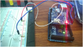
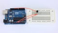
Wire It Up
The wiring for this project is pretty simple as the NES controller’s connector end makes it easy to probe breadboard wires into. Of course, if you would like something more secure, it is suggested to buy an NES controller extension cable and cut the male end of it off so that you can easily grab the wires from there. That way, you can directly insert that into the Arduino while having a secure connection and the controller’s end.
Below shows how to wire this gem up.

As you can see, the controller only needs 5 of its 7 pins interfaced to. Two for power (+5V and GND), one for latching the button states (D2), one for clocking the button states (D3), and one for reading the serial data of button states (D4).
Arduino Code
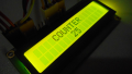
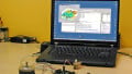
This code is heavily commented to describe the flow of state and order of operation. At the end of all of this, you will see the button states pop up in the serial monitor. The code within the serial monitor will give you a clear idea on how you may interface this to your next doomsday device harmless electronics project. The Arduino code here should coincide well with the Theory section and it should be a thorough step-by-step process, however, if you need more explanation, please comment below. The forums are also a very good place to ask questions in case you would like a faster response.
/*
================================================================================

    File........... NES Controller Test Code
    Purpose........ To demonstrate how to interface to an NES controller
    Author......... Joseph Corleto
    E-mail......... corleto.joseph @ gmail.com
    Started........ 04/13/2016
    Finished....... 04/14/2016
    Updated........ --/--/----

================================================================================
   Notes
================================================================================
- The NES controller contains one 8-bit 4021 shift register inside.

- This register takes parallel inputs and converts them into a serial output.

- This code first latches the data and then shifts in the first bit on the data line.
  Then it clocks and shifts in on the data line until all bits are received.

- What is debugged are the button states of the NES controller.

- A logical "1" means the button is not pressed. A logical "0" means the button is
  pressed.

- This code shifts the first bit of data into the LSB.

- The order of shifting for the buttons is shown in the table below:

				Bit# | Button
				--------------
				  0  |   A
				--------------
				  1  |   B
				--------------
				  2  | Select
				--------------
 		                  3  | Start
				--------------
				  4  |   Up
				--------------
				  5  |  Down
				--------------
				  6  |  Left
				--------------
				  7  | Right
				--------------

- The NES controller pinout is shown below (looking into controllers
  connector end):
	  __________
	 /	    |
	/       O 1 |	1 - Ground
        |           |	2 - Clock
	| 7 O   O 2 |   3 - Latch
	|           |	4 - Data Out
	| 6 O   O 3 |	5 - No Connection
	|           |   6 - No Connection
	| 5 O   O 4 |   7 - +5V
	|___________|

- Please visit www.allaboutcircuits.com to search for complete article!

================================================================================
  Updates
================================================================================
*/

//===============================================================================
//  Header Files
//===============================================================================

//===============================================================================
//  Constants
//===============================================================================
// Here we have a bunch of constants that will become clearer when we look at the
// readNesController() function. Basically, we will use these contents to clear
// a bit. These are chosen according to the table above.
const int A_BUTTON         = 0;
const int B_BUTTON         = 1;
const int SELECT_BUTTON    = 2;
const int START_BUTTON     = 3;
const int UP_BUTTON        = 4;
const int DOWN_BUTTON      = 5;
const int LEFT_BUTTON      = 6;
const int RIGHT_BUTTON     = 7;

//===============================================================================
//  Variables
//===============================================================================
byte nesRegister  = 0;    // We will use this to hold current button states

//===============================================================================
//  Pin Declarations
//===============================================================================
//Inputs:
int nesData       = 4;    // The data pin for the NES controller

//Outputs:
int nesClock      = 2;    // The clock pin for the NES controller
int nesLatch      = 3;    // The latch pin for the NES controller

//===============================================================================
//  Initialization
//===============================================================================
void setup()
{
  // Initialize serial port speed for the serial terminal
  Serial.begin(9600);

  // Set appropriate pins to inputs
  pinMode(nesData, INPUT);

  // Set appropriate pins to outputs
  pinMode(nesClock, OUTPUT);
  pinMode(nesLatch, OUTPUT);

  // Set initial states
  digitalWrite(nesClock, LOW);
  digitalWrite(nesLatch, LOW);
}

//===============================================================================
//  Main
//===============================================================================
void loop()
{
  // This function call will return the states of all NES controller's register
  // in a nice 8 bit variable format. Remember to refer to the table and
  // constants above for which button maps where!
  nesRegister = readNesController();

  // Slight delay before we debug what was pressed so we don't spam the
  // serial monitor.
  delay(180);

  // To give you an idea on how to use this data to control things for your
  // next project, look through the serial terminal code below. Basically,
  // just choose a bit to look at and decide what to do whether HIGH (not pushed)
  // or LOW (pushed). What is nice about this test code is that we mapped all
  // of the bits to the actual button name so no useless memorizing!
  if (bitRead(nesRegister, A_BUTTON) == 0)
    Serial.println("JUMP!");

  if (bitRead(nesRegister, B_BUTTON) == 0)
    Serial.println("PUNCH!");

  if (bitRead(nesRegister, START_BUTTON) == 0)
    Serial.println("DOOMSDAY ACTIVATED");

  if (bitRead(nesRegister, SELECT_BUTTON) == 0)
    Serial.println("WHY DON'T YOU MAP SOMETHING HERE?");

  if (bitRead(nesRegister, UP_BUTTON) == 0)
    Serial.println("...OR HERE?");

  if (bitRead(nesRegister, DOWN_BUTTON) == 0)
    Serial.println("PLAY WITH THE CODE ALREADY!");

  if (bitRead(nesRegister, LEFT_BUTTON) == 0)
    Serial.println("MAKE SOMETHING WITH THIS!");

  if (bitRead(nesRegister, RIGHT_BUTTON) == 0)
    Serial.println("GOOD LUCK WITH YOUR PROJECT ");
}

//===============================================================================
//  Functions
//===============================================================================
///////////////////////
// readNesController //
///////////////////////
byte readNesController()
{
  // Pre-load a variable with all 1's which assumes all buttons are not
  // pressed. But while we cycle through the bits, if we detect a LOW, which is
  // a 0, we clear that bit. In the end, we find all the buttons states at once.
  int tempData = 255;

  // Quickly pulse the nesLatch pin so that the register grab what it see on
  // its parallel data pins.
  digitalWrite(nesLatch, HIGH);
  digitalWrite(nesLatch, LOW);

  // Upon latching, the first bit is available to look at, which is the state
  // of the A button. We see if it is low, and if it is, we clear out variable's
  // first bit to indicate this is so.
  if (digitalRead(nesData) == LOW)
    bitClear(tempData, A_BUTTON);

  // Clock the next bit which is the B button and determine its state just like
  // we did above.
  digitalWrite(nesClock, HIGH);
  digitalWrite(nesClock, LOW);
  if (digitalRead(nesData) == LOW)
    bitClear(tempData, B_BUTTON);

  // Now do this for the rest of them!

  // Select button
  digitalWrite(nesClock, HIGH);
  digitalWrite(nesClock, LOW);
  if (digitalRead(nesData) == LOW)
    bitClear(tempData, SELECT_BUTTON);

  // Start button
  digitalWrite(nesClock, HIGH);
  digitalWrite(nesClock, LOW);
  if (digitalRead(nesData) == LOW)
    bitClear(tempData, START_BUTTON);

  // Up button
  digitalWrite(nesClock, HIGH);
  digitalWrite(nesClock, LOW);
  if (digitalRead(nesData) == LOW)
    bitClear(tempData, UP_BUTTON);

  // Down button
  digitalWrite(nesClock, HIGH);
  digitalWrite(nesClock, LOW);
  if (digitalRead(nesData) == LOW)
    bitClear(tempData, DOWN_BUTTON);

  // Left button
  digitalWrite(nesClock, HIGH);
  digitalWrite(nesClock, LOW);
  if (digitalRead(nesData) == LOW)
    bitClear(tempData, LEFT_BUTTON);

  // Right button
  digitalWrite(nesClock, HIGH);
  digitalWrite(nesClock, LOW);
  if (digitalRead(nesData) == LOW)
    bitClear(tempData, RIGHT_BUTTON);

  // After all of this, we now have our variable all bundled up
  // with all of the NES button states.*/
  return tempData;
}
Future Thoughts
If you enjoyed this project and learned how to interface to the NES controller well, the SNES controller is pretty much the same idea, but with a bigger shift register (16 bits instead of 8 bits).
Happy hacking!
Give this project a try for yourself! Get the BOM.


Simple and straight forward, can’t wait to try it.
as recognized control windows ? / Como hago funcionar el control con Windows una vez pasado el codigo al arduino??